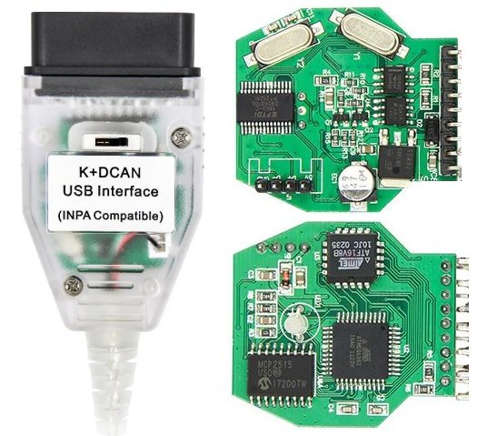
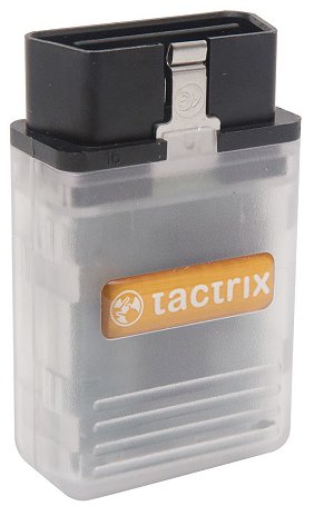
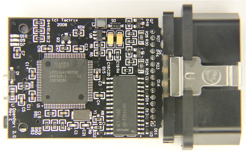
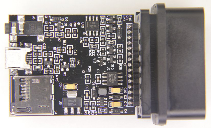
HUD ECU Hacker can scan all ECU's from all motorbikes, ATV's, cars and trucks if they support the OBD2 protocol.
OBD2 also permits to see and clear the fault codes (DTC = Diagnostic Trouble Codes) that the ECU is reporting.
OBD2 is supported by all newer vehicles, but gives few details for the service technician
because it's only purpose is to control the compliance of exhaust emission laws.
They implement the same AT commands as genuine ELM327 adapters and have additional ST commands.
If you want to use an ELM327 adapter you should ONLY buy it from Scantool or OBDLink.
My adapter was sold with a very old firmware. Don't forget to update the firmware.
Even in a genuine OBDLink adapter I found a severe bug.
Even with the genuine OBDLink adapters the ECU Emulator will not work.
Chinese vLinker adapters:
Vgate offers their vLinker FS adapter
with the MIC3322 chip. Download Datasheet (PDF)
They are cheaper ($25 USD) than OBDLink. They also support the extended ST command set.
I did not test these adapters. They may work well or have lots of bugs as usual in Chinese products.
ELM327 adapters are a misdesign. They are also significantly slower than the other adapters.
They have too many commands which makes programming complicated.
Instead of leaving the intelligence in the controlling software (as J2534 adapters do) all the intelligence is in the chip.
The chip must be configured with hundreds of commands.
Instead of transmitting binary data directly (as J2534 adapters do), they use ASCII strings, which is simply a bad design.
ISO 15765 data is passed by the adapter with missing CAN ID or must be parsed in the controlling software (STUPID design!)
Instead of using internally an USB capable processor (as J2534 adapters do) they convert USB first to RS232 which is slower
and the COM port must be configured with the correct baudrate, while J2534 adapters neither need COM ports nor baudrates.
If you have very fast CAN bus traffic the ELM327 loses packets because the internal serial connection is too slow.
Another issue is that the ELM327 can store configuration in non-volatile memory resulting in not predetermined behaviour.
None of the ELM327 adapters (not even the genuine) supports the CAN Raw protocol.
The internal buffer in the adapter is too small for high speed CAN bus traffic. You will get BUFFER FULL errors.
If you already have an ELM327 or OBDLink adapter study the Trace pane to see how many errors you get.
But do not buy an ELM327 adapter! See summary above.
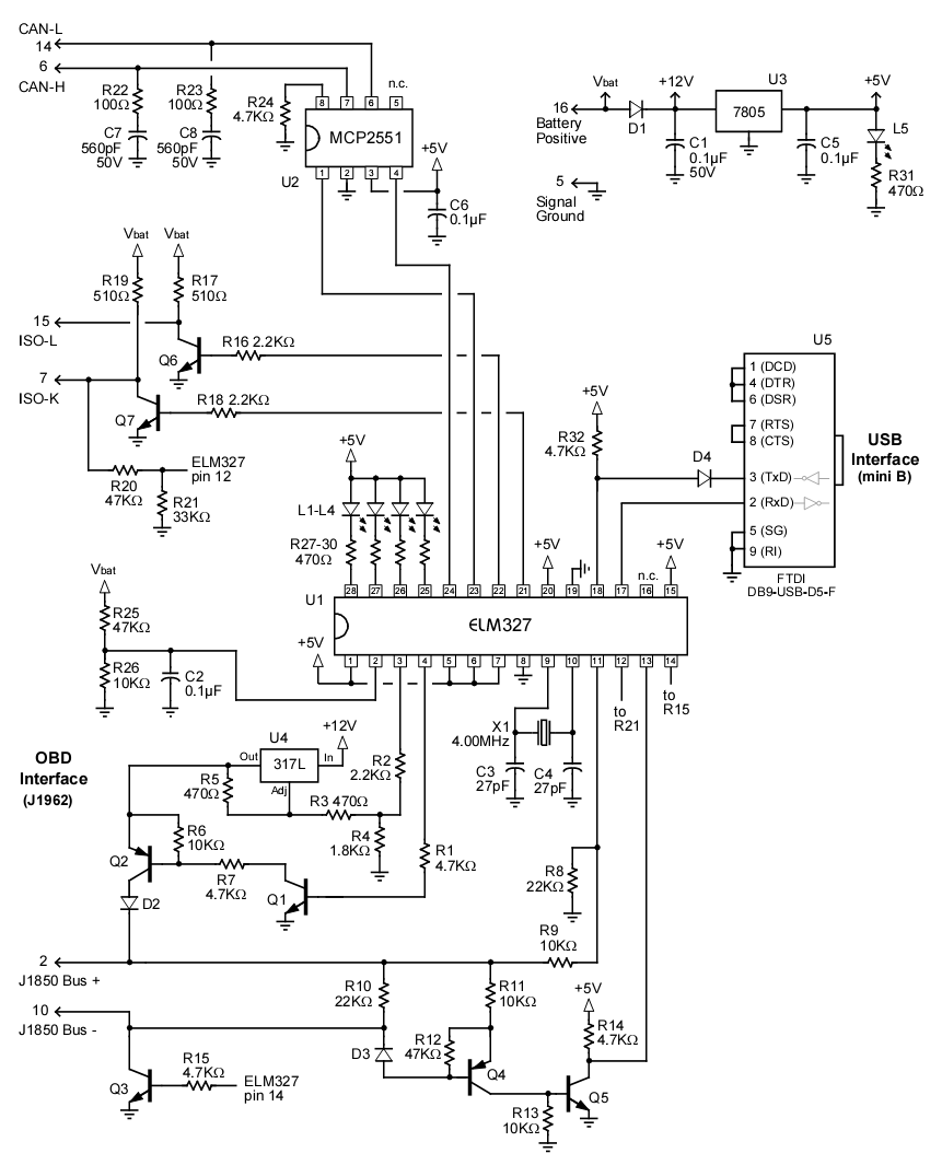
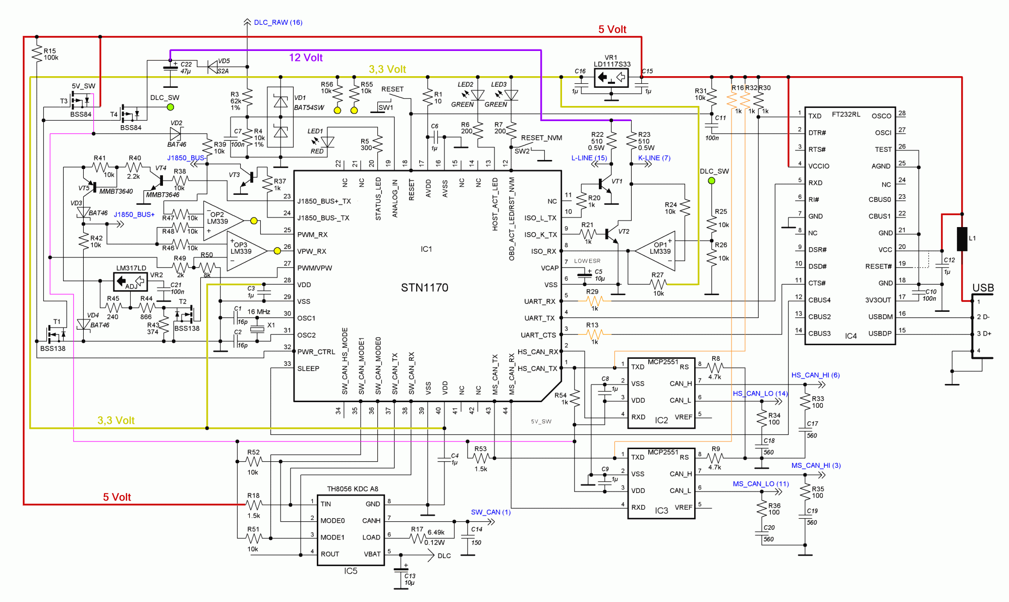
Diagrams of a genuine adapters:
EML327
Show Full Size
OBDLink
Show Full Size
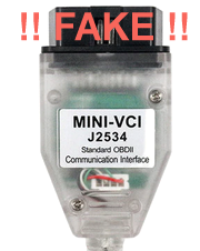
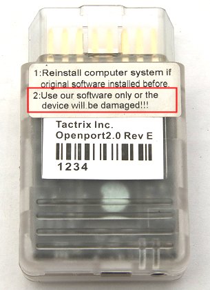
Counterfeit ELM327 Adapters
Do NOT buy any of the cheap Chinese ELM327 adapters which are sold on Amazon or eBay!
They are all fake and work only partially. Many ELM327 commands are buggy or even not implemented at all.
If you see one of the following errors in the HUD ECU Hacker Trace pane, the Chinese have betrayed you:
The buffer of the fake adapters is so tiny that it cannot even receive a 128 byte ECU response!
So you can only scan the OBD2 commands which give few information, but not the detailed vendor specific commands.
You will see none of the above errors if you use a genuine OBDLink adapter.
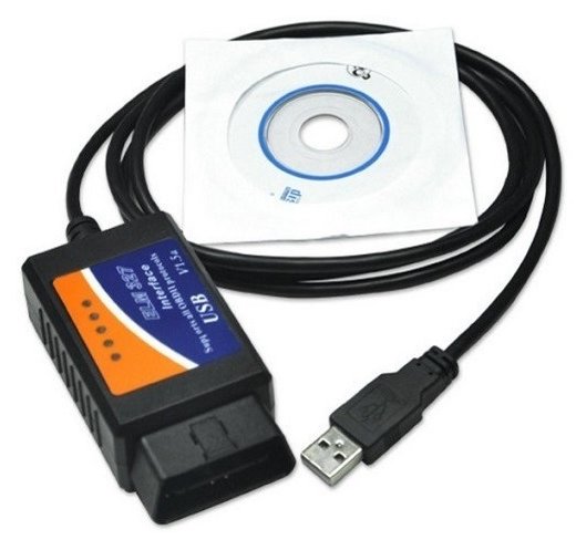
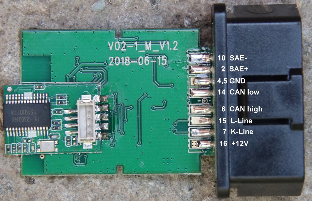
Counterfeit ELM327 USB Adapters
Chinese Clone
Show Full Size
Chinese Clone
Show Full Size
Some chinese USB adapters use a counterfeit PL2303 chip (right photo) which converts from USB to RS232.
On Windows XP and Windows 7 this works perfectly.
But on Windows 8, 10 and 11 the latest drivers from Prolific detect the counterfeit chip and refuse to work.
The driver returns the undocumented Error 433: "A device which does not exist was specified."
If you connect the adapter and Windows 10 does not find an installed driver it downloads the latest version 3.8
from Windows Update and you will see a yellow exclamation mark or a 'PHASED OUT' error:
Do not use the drivers from a CD or from Windows Update.
I have implemented the driver installation into the toolbar at the top of HUD ECU Hacker.
Install the Prolific driver version 3.3 from 2008 which also works on Windows 8, 10 and 11.
Installing a Bluetooth Adapter
Follow these steps on Windows 10 to add a bluetooth adapter: (on Windows 7 it is similar)
Show Full Size
If it was successful you see 2 COM ports in the combobox 'Port:' in HUD ECU Hacker:
Select the Outgoing serial port which is connected to the bluetooth device "OBDII".
The Incoming serial port is useless.
I do NOT recommend to buy a bluetooth adapter, no matter if OBDlink or Chinese clone.
Bluetooth uses the same frequencies as Wifi. You will have interference.
If you want a fail-safe connection to your adapter, buy a USB adapter!
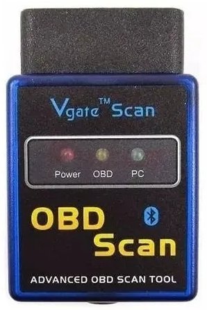
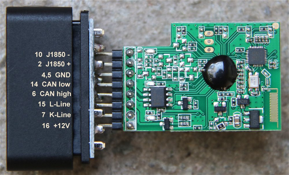
Counterfeit ELM327 Bluetooth Adapters
Chinese Clone
Show Full Size
Chinese Clone
Show Full Size
On the right photo you see that there are several SMD parts missing (4 transistors and 16 passive components).
This means that the J1850 bus will not work. Only CAN and K-Line are implemented.
If a vendor sells this as a universal ELM327 adapter, this is a fraud.
However, the J1850 bus was used by older GM and Ford vehicles, but is not used in modern cars anymore.
Counterfeit ELM327 WIFI Adapters
These adapters are the most stupid design because they represent a WIFI access point.
Mostly they respond on the fix IP address 192.168.0.10 and port 35000 without WIFI password.
The problem is that you must disconnect your notebook from your router to connect it to the adapter.
So after connecting to the OBD adapter you lose internet access.
The signal strength and maximum distance between computer and adapter are worse than with Bluetooth adapters.
The adapter uses the most used Wifi Channel 11. So conficts with your or your neighbour's router are probable.
There is absolutely no reason why should buy these adapters.
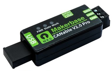
Option 6: CANable 2.0 Adapter
MKS Makerbase
Show Full Size
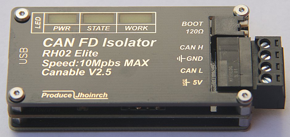
Jhoinrch RH02
Show Full Size
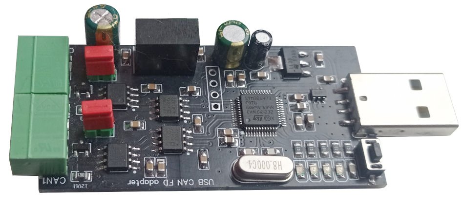
CAN-Module Dual
Show Full Size
The CANable 2.0 family are several cheap (from $15 US) adapters only for CAN bus.
They have an ARM Cortex-M4 processor like STM32G431 with 160 MHz clock.
Mostly they have a switch to turn on a 120 Ω termination resistor. Turn this off when you connect to a vehicle.
There are 2 open-source firmware versions available: Slcan and Candlelight.
But the legacy firmwares from Github have several issues:
If CAN bus is not working, you will never know what is wrong because error reporting is not implemented.
The Candlelight firmware is compete crap. Not even the driver is installed correctly.
There is a long list of problems with the legacy firmware.
Therefore I worked 3 months to write a new high quality Slcan and Candlelight firmware.
The new firmware version CANable 2.5 from ElmüSoft fixes a ton of bugs and adds many new useful features.
HUD ECU Hacker fully supports all the new features, however the new firmware is still 100% backwards compatible.
I strongly recommend that you use the firmware updater in HUD ECU Hacker to upgrade your CANable.
Please read the detailed manual about the new CANable 2.5 firmware with CAN FD support.
There you also find the links where to buy these adapters.
But even if you have an old CANable 1.0 adapter you can use it with HUD ECU Hacker.
However you will have to live with the restrictions: limited features, no CAN FD support, no firmware update possible.
Option 7: UsbCAN Adapter (deprecated)
Show Full Size
If you already have a Chinese ZLG (Polaris) UsbCAN adapter, you can use it with HUD ECU Hacker.
However, do not buy one because it supports only CAN bus and the driver is worst Chinese 'quality' with many bugs.
Most of the pins are fake. Only the uppermost (CAN0H and CAN0L) are connected internally.
The LED's are extremely stupid: Red LED blinking means OK. Green LED illuminated means CAN bus error.
To install the driver click the toolbar button Install USB Driver in HUD ECU Hacker.
K-Line
Show Full Size
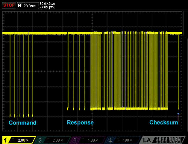
Many years the simple open-collector K-Line connection was the standard of communication with the ECU.
A serial protocol is used for a bidrectional data transfer over a single wire which allows speeds up to a maximum of 50 kBaud.
The right screenshot shows the K-Line communication to the Delphi MT05 ECU on an oscilloscope.
KW 1281 Protocol
KW 1281 is a proprietary Bosch/Volkswagen protocol and the oldest protocol implemented in HUD ECU Hacker.
It was used in old ECU's from Bosch (Made in Germany) in cars from Volkswagen and Opel.
KW 1281 uses K-Line with 5-Baud Init and 9600 baud data transfer.
These are the transferred bytes that you see in the Trace pane when reading an analog ECU input (sensor):
Command (from PC):
04 61 ( 08 02 ) 03
Response (from ECU):
05 62 ( FB 55 01 ) 03
But invisibly in the background the double amount of bytes is transferred.
Blue: Bytes sent by the tester (HUD ECU Hacker)
Green: Bytes sent by the ECU
Command
Response
Header 1
04
Packet Length
Header 1
05
Packet Length
FB
Inverted: FB = 04 XOR FF
FA
Inverted: FA = 05 XOR FF
Header 2
61
Counter
Header 2
62
Counter + 1
9E
Inverted: 9E = 61 XOR FF
9D
Inverted: 9D = 62 XOR FF
Payload 1
08
Command Read ADC Channel
Payload 1
FB
Response Read ADC Channel
F7
Inverted: F7 = 08 XOR FF
04
Inverted: 04 = FB XOR FF
Payload 2
02
Channel no. 2
Payload 2
55
ADC Value High Byte
FD
Inverted: FD = 02 XOR FF
AA
Inverted: AA = 55 XOR FF
ETX
03
End of Transfer
Payload 3
01
ADC Value Low Byte
FE
Inverted: FE = 01 XOR FF
ETX
03
End of Transfer
As you see the KW 1281 protocol is very stupidly designed:
Each and every received byte is sent back inverted which produces 100% overhead.
Addionally K-Line adapters have a very bad performance when single bytes are transferred one by one over USB.
The result of this inefficent transfer is that KW 1281 is much slower than modern ISO protocols.
IMPORTANT: The Bosch ECU's are extremely primitive. They don't have a mechanism to handle transfer errors.
If anything goes wrong during the transfer the ECU sends 4 garbage bytes and then stops communication.
Timing is very critical. If an expected byte needs longer than 40 ms the ECU blocks itself and does not respond anymore.
To avoid timing problems do not run processes on your computer that consume much CPU.
ISO 9141 Protocol
The ISO 9141 protocol is the oldest of the standardized OBD protocols. It is quite primitive.
The data transfer on K-Line (Pin 7) is like RS-232, sending the least significant bit first, but the voltage is inverted.
Show Full Size
ISO 9141 uses the extremely slow 5 Baud Init to wake up the ECU. It takes 2 seconds to transmit the address byte (0x33).
Some ECU's require this 5 Baud Init to be sent additionally on L-Line (Pin 15).
5-Baud Initialization
Sender
Data
Baudrate
Meaning
Tester
0x33
5 Baud
Address
ECU
0x55
10400 Baud
Synchronization
ECU
0x08 (0x94)
10400 Baud
Keyword 1
ECU
0x08 (0x94)
10400 Baud
Keyword 2
Tester
0xF7 (0x6B)
10400 Baud
Keyword 2 (inverted: F7 = 08 XOR FF)
ECU
0xCC
10400 Baud
Address (inverted: CC = 33 XOR FF)
Tester
Packet
10400 Baud
First Command
Next you see the first OBD2 command 01 00 (Request supported PID's) and the response from the ECU.
The command is embedded into a packet which starts with a header and ends with a checksum.
Command (from PC):
68 6A F1 ( 01 00 ) C4
Response (from ECU):
48 6B 11 ( 41 00 BE 36 B0 03 ) A9
OBD2 Command '01 00'
Response (1...7 data bytes)
Header 1
68
Fix value
Header 1
48
Fix value
Header 2
6A
Fix value
Header 2
6B
Fix value
Header 3
F1
Source address (Tester)
Header 3
11
Source address (ECU)
Payload 1
01
OBD2 Service 1
Payload 1
41
Service confirmation = 01 + 40
Payload 2
00
PID 0
Payload 2
00
PID confirmation
Checksum
C4
68+6A+F1+01+00 = C4
Payload 3
BE
8 Bits encoding supported PID's
Payload 4
36
8 Bits encoding supported PID's
Payload 5
B0
8 Bits encoding supported PID's
Payload 6
03
8 Bits encoding supported PID's
Checksum
A9
48+6B+11+41+00+BE+36+B0+03 = A9
ISO 9141 does not define error codes.
The ECU simply does not respond when it does not understand a command.
ISO 14230 Protocol
The Keyword 2000 protocol (KWP 2000) is defined in ISO 14230. It offers much more functionality than ISO 9141.
ISO 14230 normally uses Fast Init to wake up the ECU.
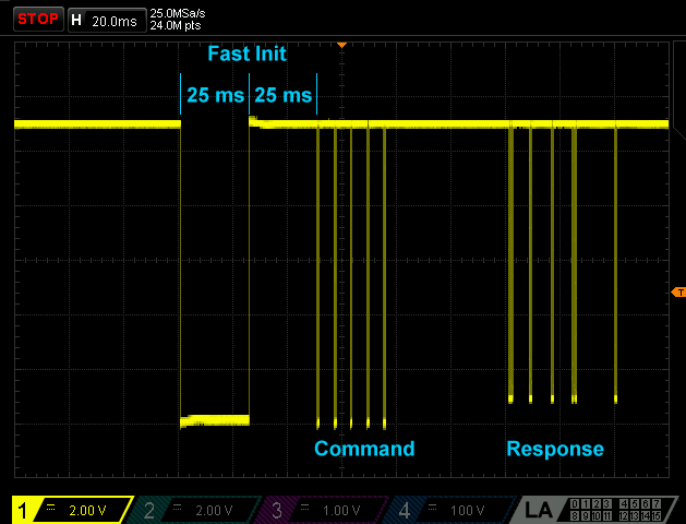
Fast Init means that the K-Line goes low for exactly 25 ms and then high for 25 ms. After that the communication starts with 10400 baud.
However, there are a few ECU's which combine the ISO 14230 protocol with 5-Baud Init.
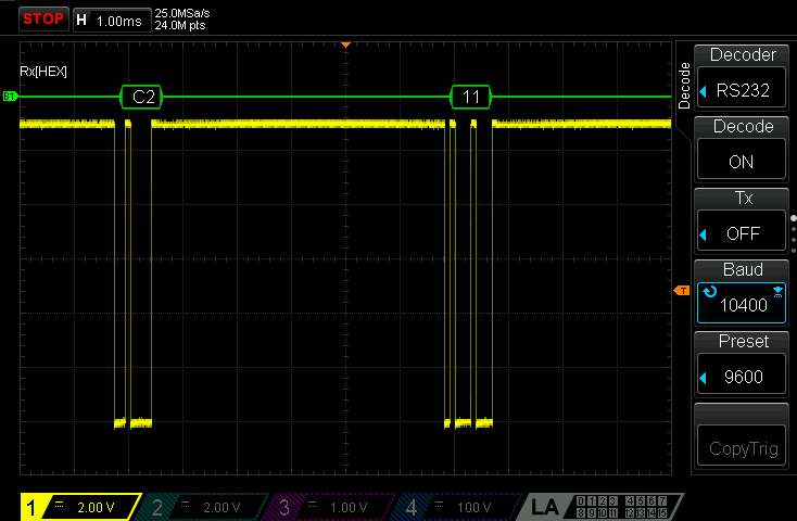
On the left you see the fast init, followed by the command 'Start Communication' and the response from the ECU.
On the right you see long pauses between the bytes which are needed if the ECU is old and very slow.
Show Full Size
Show Full Size
In detail the command 'Start Communication' (Service = 81) looks like this:
Command (from PC):
81 11 F1 ( 81 ) 04
Response (from ECU):
83 F1 11 ( C1 EF 8F ) C4
The Delphi MT05 uses the address 11. The application on the PC (the tester) uses the address F1.
The MT05 responds with 2 key bytesEF and 8F which define how the ECU wants the commands to be formatted.
They define how to transmit the packet length and if the source/target addresses are to be sent.
You see the meaning of the key bytes in the Trace pane in magenta when connecting.
Command 'Start Communication'
Response Short (1...63 data bytes)
Header 1
81
80 + length of data (1 byte)
Header 1
83
80 + length of data (3 bytes)
Header 2
11
Destination address (ECU)
Header 2
F1
Destination address (tester)
Header 3
F1
Source address (tester)
Header 3
11
Source address (ECU)
Payload 1
81
Service 'Start Communication'
Payload 1
C1
Service confirmation = 81 + 40
Checksum
04
81+11+F1+81 = 04
Payload 2
EF
Key byte 1 (bit flags)
Payload 3
8F
Key byte 2 (always 0x8F)
Checksum
C4
83+F1+11+C1+EF+8F = C4
The first header byte is called format byte.
It may contain the packet length and it's bits define if addresses are sent and the type of addresses (physical, functional).
To simplify reading the binary data HUD ECU Hacker displays the payload bytes in parenthesis in the Trace pane.
The other bytes (header + checksum) are not really interesting as they are generated automatically.
Command (from PC):
81 11 F1 ( 81 ) 04
Response (from ECU):
83 F1 11 ( C1 EF 8F ) C4
The following table shows a long response (102 data bytes) which contains an additional length byte (header 4).
Command 'Read Data'
Response Long (64...255 data bytes)
Header 1
82
80 + length of data (2 byte)
Header 1
80
Extra length byte follows
Header 2
11
Destination address (ECU)
Header 2
F1
Destination address (tester)
Header 3
F1
Source address (tester)
Header 3
11
Source address (ECU)
Payload 1
21
Service 'Read Data'
Header 4
66
Length of data (102 byte)
Payload 2
01
Subfunction 1
Payload 1
61
Service confirmation = 21 + 40
Checksum
A6
82+11+F1+21+01 = A6
Payload 2
01
Subfunction confirmation = 01
Payload 3
...
Parameter raw data byte 1
Payload 102
...
Parameter raw data byte 100
Checksum
...
80+F1+11+66+61+01+...
HUD ECU Hacker tries first to connect with the physical address defined in the parameter XML file (Default = 0x11).
If this fails it waits 5 seconds and tries again with the functional address 0x33.
A physical address (format byte contains 0x80) means that one specific device on a bus is addressed.
A functional address (format byte contains 0xC0) is like a broadcast address to a group of devices.
There are functional addresses for Steering Controllers, ABS Systems, Air Condition, Audio, Lightning, etc.
The functional address 0x33 is used to address "Engine Controllers" (ECUs).
As normally only one ECU is connected this can be used when the physical ECU address is unknown.
As you see here the ECU responds to the functional address 0x33 with it's physical address 0x11:
Command (from PC):
C1 33 F1 ( 81 ) 66
Response (from ECU):
83 F1 11 ( C1 EF 8F ) C4
The Delphi MT05 does not need functional addressing, but there are strange ECU's which do not respond to their own physical address!
Errors
ISO 14230 defines several error codes which the ECU can return.
If the ECU does not understand a command it sends 7F (failure) followed by the service and the error code.
Keep-Alive
If the ECU does not receive commands it switches to sleep mode after 5 seconds.
While HUD ECU Hacker is polling data this will never happen because polling takes place 3 to 5 times per second.
Only if you switch to manually enter commands (in the Trace pane), polling stops and HUD ECU Hacker sends a Keep-Alive every 3 seconds.
Command (from PC):
81 11 F1 ( 3E ) C1
Response (from ECU):
81 F1 11 ( 7E ) 01
Honda Protocol
Honda uses an undocumented proprietary protocol over K-Line at 10400 baud.
A pulse of 70 ms similar to the Fast Init of ISO14230 is sent to wake up the ECU before communication starts.
Command (from PC):
72 05 ( 00 F0 ) 99
Response (from ECU):
02 04 ( 00 ) FA
Command 'Initialize'
Response
Header 1
72
Command
Header 1
02
Command AND 0x0F
Header 2
05
Byte count in this packet
Header 2
04
Byte count in this packet
Payload 1
00
Parameter byte 1
Payload 1
00
Response byte 1
Payload 2
F0
Parameter byte 2
Checksum
FA
02+04+00+FA = 00
Checksum
99
72+05+00+F0+99 = 00
CAN Bus
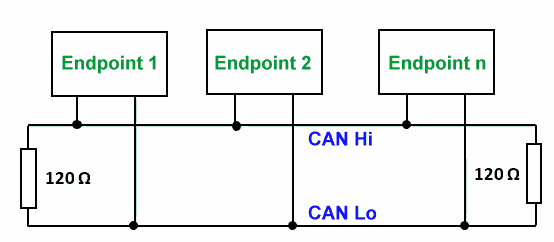
Newer vehicles are equipped with CAN bus which uses 2 wires (CAN Hi and CAN Lo) and runs mostly at 250 or 500 kBaud.
Many controllers and sensors may be connected to the same bus. Each endpoint has at least one unique ID.
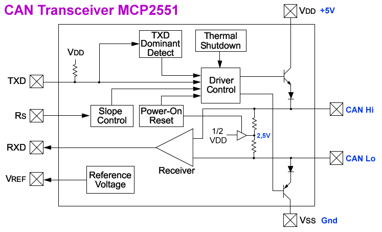
The neutral voltage on CAN bus is 2.5 Volt. Each endpoint has a transmitter which pulls CAN Hi up and CAN Lo down.
The receiver measures the difference between CAN Hi and CAN Lo which makes CAN robust against electromagnetic interference.
Show Full Size
Show Full Size
Additionally an intelligent arbitration system in each endpoint detects if 2 endpoints try to send data at the same time.
In case of such a collision it is clearly defined which enpoint has priority.
The endpoint which loses arbitration must stop transmission and try to send the packet again later.
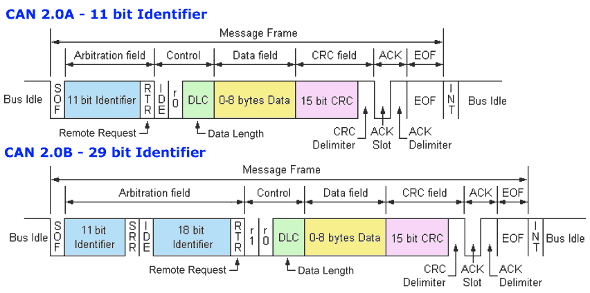
Below you see a raw CAN frame which contains the identifier (11 bit or 29 bit) and max 8 data bytes.
Data transfer is very robust because a 15 bit CRC assures that each frame is received without error.
If you have to analyze problems with CAN bus and you have an oscilloscope that can connect to a computer over USB,
you can use my open source software Oszi Waveform Analyzer
which converts your oscilloscope into a logic analyzer.
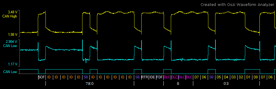
After A/D conversion of the analog inputs the CAN bus decoder shows the bits of the CAN packets, as you see here:
Show Full Size
Show Full Size
The CAN bus Identifier (ID) is similar to the ECU address in the ISO 14230 protocol.
Some motorbike ECU's permanently broadcast data to the CAN bus.
This is mostly engine speed, coolant temperature and MIL lamp status which the dashboard displays to the driver.
In motorbikes with ABS system you may also see the ABS ECU broadcasting the front and rear wheel speed.
As you see in the diagram above there is an ACK Slot in the CAN frame.
The idea is that the receiver of a packet sets the ACK bit to acknowledge that it has received the packet.
If the packet was not acknowledged the sender may send it again.
If you see the same CAN packet beeing sent over and over again within one millisecond the cause may be that nobody has acknowledged it.
But broadcast messages are normally sent in fix intervals and need not necessarily be acknowledged.
ELM327, OBDLink and UsbCAN adapters allow to chose if you want to silently monitor the CAN bus without interfering by not setting the ACK bit.
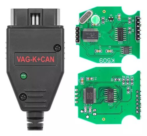
However J2534 and VAG K+CAN adapters always acknowledge all packets on the bus. You cannot turn this off.
CAN Raw Protocol
If your ECU uses the CAN Raw protocol you will see completely undocumented and proprietary packets which differ with each vendor.
Mostly these ECU's have one address (CAN ID) on which they receive commands and multiple addresses on which they send responses.
Here you see the CAN Raw traffic of the Deni 1700 ECU which broadcasts data on multiple CAN ID's:
104: 5D C4 C4 82 00 7F 34 03
105: 00 00 20 00 00 98 4B 76
106: 00 00 00 00 00 00 00 B4
107: 90 80 E8 03 10 27 01 29
108: 00 F0 64 00 00 00 64 00
109: 7F 02 00 00 7F 03 00 00
110: 00 00 00 00 00 00 00 00
111: 64 00 64 00 00 00 00 00
CAN FD Protocol
CAN FD stands for "Flexible Datarate". CAN FD extends the classic CAN protocol by 2 main features:
The data bytes in the CAN packet are transmitted with a higher baudrate than the ID, CRC and the other bits.
For example the baudrate may be 500 kBaud, while the data bytes are transmitted with 2 Mega baud.
A packet can transmit a maximum of 64 data bytes.
HUD ECU Hacker supports CAN FD, but most adapters do not.
If you want to experiment with CAN FD you need a CANable adapter and must upload the CANable 2.5 firmware.
CAN Bus Filter
If you sniff the CAN bus traffic in a car or a truck you get a tremendous amount of data.
CAN bus traffic comes from ECU, ABS, air bags, seat belts, multimedia, door sensors, window- and mirror control, and more.
A filter and a mask will be needed to exclude all traffic on the CAN bus except with the ECU.
But even if you only connect one ECU which autonomously sends packets you may want to exlude them from the sniffed data.
The filtering also tells the adapter which packets to acknowledge (set the bit in the ACK slot of the CAN frame).
If HUD ECU Hacker runs in sniff mode it will never modify the ACK bit.
Otherwise, when communicating with the ECU or in Emulator mode the received packets must be ACKnowledged.
If a CAN packet is not ACK'ed by the receiver the sender assumes that it was not received and sends it again.
If a CAN packet is not ACK'ed mutiple times the sender generates an error and stops the communication.
For CAN Raw protocol you must enter RespFilter and RespMask in the parameter XML file.
For ISO 15765 these are not needed. You enter a fix RespID instead.
For Sniffing you can use the following window to define the filter and mask:
All checkboxes have a tooltip which explains the purpose.
In the field 'Response ID' enter an ID on which the ECU responds and the filter and mask will be calculated automatically.
Example 1.)
If you know the ECU ID enter it into the field 'Response ID'.
If you enter 7E8, the filter and mask will be calculated as 7E8 and 7FF.
Example 2.)
Otherwise use the letter 'X' to specify that a digit does not matter (e.g. 7EX). A digit corresponds to 4 bits.
If you enter 7EX, the filter and mask will be calculated as 7E0 and 7F0.
Example 3.)
If the precision of 1 digit = 4 bits = 16 matches is not enough you must enter filter and mask manually.
Example 1
Example 2
Example 3
Field 'Response ID'
7E8 = 111 1110 1000
7EX = 111 1110 XXXX
empty
Field 'Response Filter'
7E8 = 111 1110 1000
7E0 = 111 11100000
7E8 = 111 1110 1000
Field 'Response Mask'
7FF = 111 1111 1111
7F0 = 111 11110000
7FC = 111 1111 1100
Received ID's
that match the
filter and mask
7E8 = 111 1110 1000
only 1 ID matches
7E0 = 111 11100000
7E1 = 111 11100001
7E2 = 111 11100010
7E3 = 111 11100011
7E4 = 111 11100100
7E5 = 111 11100101
7E6 = 111 11100110
7E7 = 111 11100111
7E8 = 111 11101000
7E9 = 111 11101001
7EA = 111 11101010
7EB = 111 11101011
7EC = 111 11101100
7ED = 111 11101101
7EE = 111 11101110
7EF = 111 11101111
16 ID's match
7E8 = 111 1110 1000
7E9 = 111 1110 1001
7EA = 111 1110 1010
7EB = 111 1110 1011
4 ID's match
Each bit in the mask which is one defines that the same bit in the filter must match the same bit in the ID of the received CAN frame.
Each bit in the mask which is zero defines that the same bit does not matter, neither in the filter nor in the ID of the received CAN frame.
If you enter ResponseID = XXX or Mask = 000 the filter is turned off and all CAN ID's will pass through.
ISO 15765 Protocol
The ISO 15765 protocol
has been developed to overcome the limit of 8 data bytes in CAN bus frames.
ISO 15765 can send messages up to 4095 data bytes in multiple CAN Raw frames.
It occupies the first data byte of each CAN frame as a control byte.
The first byte may define that the frame is a SF (Single Frame) which transmits only 7 data bytes.
Or a FF (First Frame) followed by multiple CF (Consecutive Frames) and FC (Flow Control Frames) transport a larger payload.
You can configure HUD ECU Hacker to show with the ISO 15765 data additionally the CAN Raw frames in the Trace pane:
Above in blue you see a 3 byte ISO 15765 command sent to the Delphi MT05.3
The next line in gray shows this command encoded as a Single Frame in a CAN Raw packet.
The ECU responds with the First Frame.
Then HUD ECU Hacker sends a Flow Control Frame.
The ECU sends two Consecutive Frames.
And finally in green you see the ISO 15765 decoded ECU response.
OBD2 compliant ECU's with 11 bit ID mostly reveive commands on address 7E0 and send responses on 7E8.
If your vehicle has more than one ECU, the second ECU may use the pair 7E1 / 7E9.
OBD2 compliant ECU's may use the range 7E0 ... 7E7 for receiving and 7E8 ... 7EF for responding.
The scantool can send a command to the broadcast address 7DF where all connected ECU's must respond with their own address.
ECU's with 29 bit ID use 18DB33F1 for broadcast and 18DAF1xx for commands and 18DAxxF1 for responses.
ECU's with ISO 15765 protocol may additionally broadcast autonomous CAN Raw packets on other addresses.
Mostly these data packets contain MIL status, engine speed and temperature which are displayed by the dashboard.
J1939 Protocol
The J1939 protocol is widely used in industry and in on-highway, construction, agriculture and forestry vehicles.
Many devices are connected to the CAN bus like ECU, brake and transmission controller, retarder, torque converter, cruise control, even joysticks.
In a truck the CAN bus controls everything from the driver cabin to the back lights of the trailer.
Driver commands are sent over CAN bus, like lowering a lift axle or a ramp in a truck or controlling the air condition in a bus.
In certain intervals most controllers send autonomously data packets with wheel speed, tire pressure, oil pressure or catalyst status.
J1939 is also used in electric vehicles where it gives details of the high voltage and temperature of battery packs, charge current, etc.
J1939 uses two baudrates: either 250 kBaud or 500 kBaud.
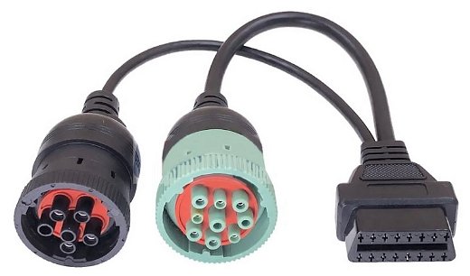
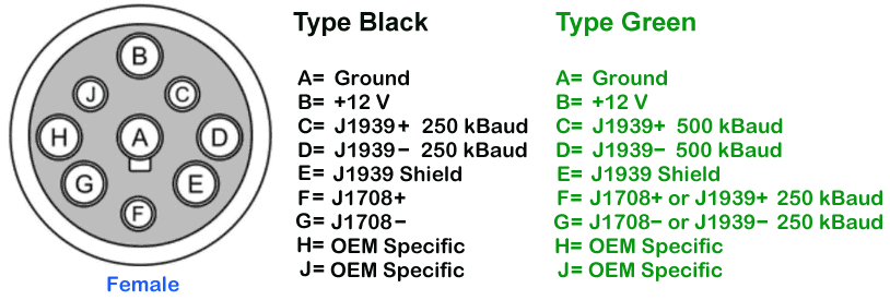
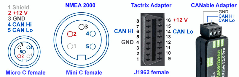
For the J1939 CAN bus you need an HD16-9-1939 adapter.
There are two versions: black and green. The pin F has a different diameter so only the correct plug will fit in.
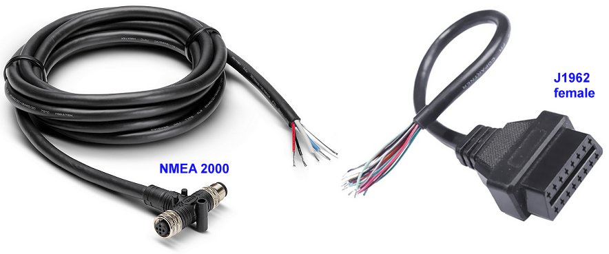
If you buy a cable like on the photo you can connect to both types of plugs.
Show Full Size
Show Full Size
When HUD ECU Hacker connects to the CAN bus it will not interfere in any way with the J1939 traffic.
One exception is when you click Clear Fault Codes wich will send a command to one CAN controller.
You can also send a broadcast request to get an Address Claim or the Diagnostic Messages from all CAN controllers.
J1939 uses CAN packets with a 29 bit identifier which contains the priority, a PGN and the source address.
The source address defines the CAN controller that sends the packet. Addresses range from 00 to FF.
Some CAN controllers have a fix address, others claim their address in the initialization phase dynamically.
The destination address is mostly broadcast which means no specific destination.
But there are also some PGN's which allow to be sent to a specific controller on the bus.
The PGN (Parameter Group Number) defines how to interpret the 8 data bytes in the packet.
Each parameter in the packet has an SPN (Suspect Parameter Number) assigned.
You find a list of all existing J1939 PGN's and SPN's at IsoBus.net.
The following example shows the controller with source address 02 sending a packet with priority 3 and PGN 61444.
The receiver has a huge database which defines for each PGN how to decode the 64 bits in the 8 data bytes.
SPN
Meaning
Start Bit
Length
Formula
Unit
899
Engine Torque Mode
0
4 bit
lookup
none
4154
Actual Engine - Percent Torque (Fractional)
4
4 bit
Raw Value / 8
%
512
Driver's Demanded Engine - Percent Torque
8
8 bit
Raw Value - 125
%
513
Actual Engine - Percent Torque
16
8 bit
Raw Value - 125
%
190
Engine Speed
24
16 bit
Raw Value / 8
rpm
1483
Source Address of Controlling Device for Engine Control
40
8 bit
none
J1939 address
1675
Engine Starter Mode
48
4 bit
lookup
none
2432
Engine Demand - Percent Torque
56
8 bit
Raw Value - 125
%
Additionally the J1939 database defines thousands of lookup values.
For example SPN 1675 defines 14 values explaining problems why the engine cannot be started:
Over temperature, immobilizer active, inhibited by transmission, engine not ready, engine already running, etc.
Most J1939 messages use the 8 data bytes that are available in a CAN bus packet.
But J1939 also provides a way to transmit messages up to 1785 bytes which consist of multiple 8 byte packets.
Therefore the J1939 Transport Protocol is used which is implemented in PGN 60160 and PGN 60416.
HUD ECU Hacker can decode 1400 messages (J1939 PGN's) with 8500 parameters (J1939 SPN's).
Show Full Size
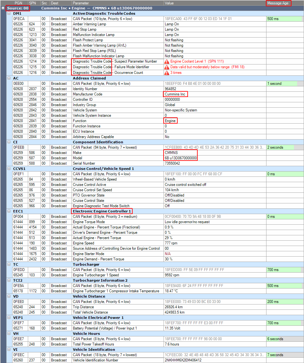
The screenshot at the left shows a small part of the J1939 CAN bus traffic of a Kenworth truck.
Pay attention to the following details:
- From address 00 a Cummins Engine Controller (ECU) sends it's operation status.
- It sends a Diagnostic Trouble Code which has occurred 3 times.
- You see the PGN 61444 "Electronic Engine Controller 1" which I explained in detail above.
- The column Message Age shows the time when the message was last seen on CAN bus or the logfile timestamp.
- The messages Address Claimed and Component Identification send details about a controller.
HUD ECU Hacker extracts the available information about each controller on CAN bus and shows it in the dark blue header:
But this works only if the messages "Address Claimed", "Component Identification" and others have appeared on CAN bus.
If you play a logfile HUD ECU Hacker scans the entire file searching these messages before playing back the log data.
If you connect to a CAN bus that is already busy you will probably miss these messages.
Click the button "Request" below in the DataGrid to broadcast a request to all CAN controllers.
The J1939 protocol can also transmit ISO 15765 traffic over the PGN's 0xDA0000 and 0xDB0000 e.g. for ECU flashing.
HUD ECU Hacker will automatically extract ISO 15765 traffic in a J1939 logfile into a separate HTML file.
NMEA 2000 Protocol
Show Full Size
The NMEA 2000 protocol adds additional messages to J1939 which are only used in marine applications.
NMEA is the National Marine Electronics Association. Like J1939 they also use PGN's, but no SPN's.
On the CAN bus of a vessel you see GPS location, water depth and temperature, wind speed,
emergency systems (DSC), identitiy (MMSI), course and location of nearby ships (AIS report), etc.
Many NMEA 2000 messages use the 8 data bytes that are available in a CAN bus packet.
But the NMEA created the "Fast Packet" which can transmit messages with up to 223 bytes.
HUD ECU Hacker can decode 350 messages (NMEA PGN's) with 3000 parameters.
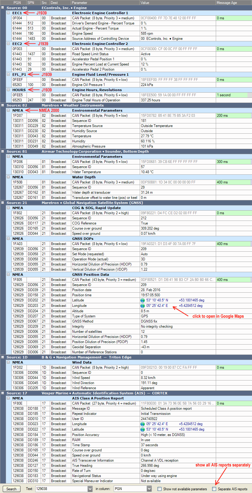
The screenshot at the left shows a small part of the NMEA 2000 CAN bus traffic of a yacht.
You can click on any GPS location (longitude + latitude) and HUD ECU Hacker opens it in Google Maps.
You can chose to see all AIS reports separately, which may be multiple hundreds, or see only the current.
HUD ECU Hacker can record logfiles and load logfiles created by other software: Linux CAN dump,
Actisense (ASCII + EBL), Yacht Devices, Garmin, Wireshark, CSV, iKonvert, PCAN View.
Normally the NMEA companies sell you expensive PC interfaces to connect to your boat.
For example Digital Yacht iKonvert or Actisense NGT-1 are extremely expensive ($245 US) and slow (only 230 kbaud).
Actisesense NMEA Reader is a very primitive software, full of bugs and hundreds of NMEA parameters are not implemented.
But HUD ECU Hacker allows you to connect with cheap ($20 US) and fast (12 MBaud) adapters: Tactrix Clone or CANable.
And you will see more than ten thousand parameters decoded correctly.
You also don't have to buy expensive CAN bus simlators anymore. HUD ECU Hacker can send any logfile to the CAN bus.
Here the CL_ 2 < 1 means that the last 2 signals are cloned the amount of times defined in signal 1.
The index of the signals is zero-based, so signal 1 is the second signal.
The byte value of CountOfZoneNumbers defines how many ZoneNumber and ZoneName are transmitted.
There are more syntax extensions implemented. Write me an email if you want to create your own DBC file.
History of HUD ECU Hacker
In 2020 my Regal Raptor 350 motorbike reported a problem. I searched for OBD2 software which can show me an error code.
But all the programs that I tested were completely uselss. They did not display any data.
Show Full Size
Show Full Size
The Regal Raptor 350 uses the Delphi MT05 ECU which is not OBD2 compliant.
Then I found a scantool that is made for this ECU.
But it is primitive and expensive ($250 US). It has only 5 buttons and shows only 2 parameters at once.
Show Full Size
Finally I found a manual of the Delphi MT05 where they mention a PC software "PCHUD" that can scan this ECU.
PCHUD ('Heads Up Display' for PC) is a very old program from Delco Electronics written in 1993 for Windows 3.
Today it is impossible to find this ancient software in internet.
There are lots of dead links and a fake PCHUD download on a chinese website that is a trojan.
I finally found it in the forum China Riders offered by the (ex)user 'katflap'.
The ancient 16 bit program PCHUD does not run on 64 bit Windows because Microsoft removed support for 16 bit applications.
If running on a 32 bit Windows in the 16 bit emulator it permanently consumes 100% of the CPU.
PCHUD is buggy, clumsy to use, cannot show all parameters at once, cannot clear fault codes, supports only K-Line adapters.
I reverse engineerd PCHUD and implemented the parameters into a my own software. HUD ECU Hacker was born.
The first version of HUD ECU Hacker, released in 2020 during the plandemic, was a modern replacement for the primitive PCHUD.
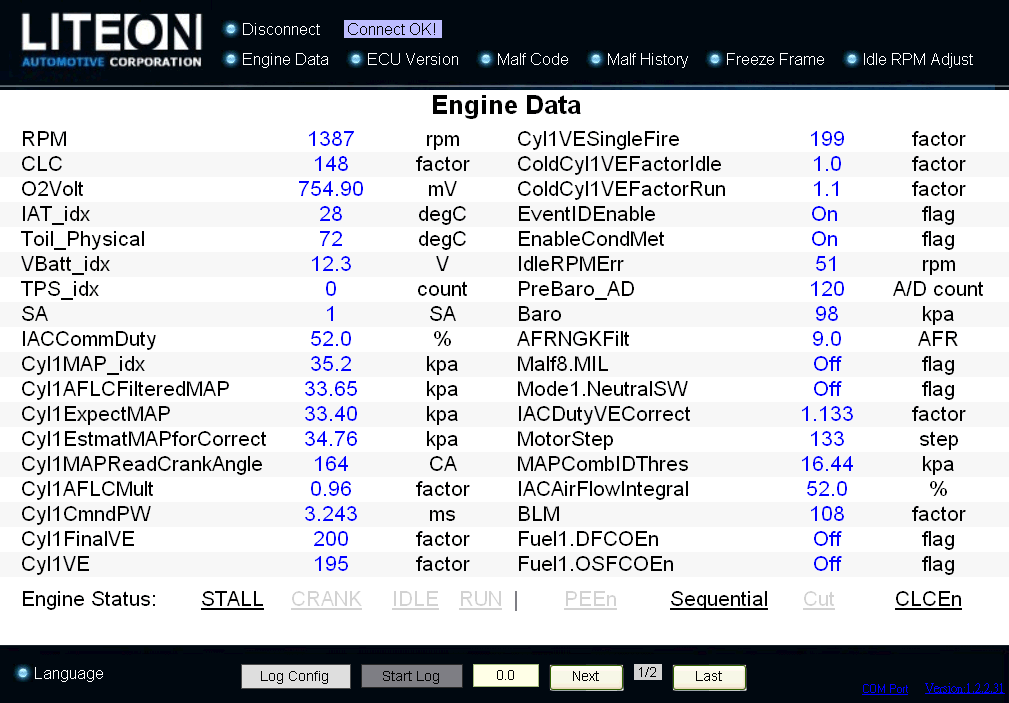
Another old software Diag Tool for the Delphi / Liteon MC21 has also been reverse engineered and replaced by HUD ECU Hacker.
Previously there was no other software available that could communicate with these proprietary ECU's.
PCHUD (MT05)
Show Full Size
DiagTool (MC21)
Show Full Size
Features of HUD ECU Hacker
runs on Windows 7, 8, 10 and 11 (not on Linux)
runs on 32 bit and 64 bit Windows
supports the adapters: K-Line, VAG K+CAN, J2534, CANable, ELM327 (USB, Bluetooth, Wifi) and UsbCAN
can install the Windows drivers for all supported adapters
supports multiple ECU models over K-Line and CAN bus
automatically detects protocol, baudrate, bus init when using autodetect mode
shows fault codes (DTC) with a text explanation
can clear fault codes (if supported by the ECU model)
shows all ECU parameters at once in a user-configurable dashboard (90 params for the MT05)
shows detailed tooltips for all parameters and their meaning
implements more than 8500 parameters for J1939 (trucks, buses, construction, agriculture and forestry vehicles)
implements more than 3000 parameters for NMEA 2000 (boats, yachts and vessels)
supports ECU tuning on a dyno with wideband O2 sensor
can be adapted to any KW 1281 / ISO 9141 / ISO 14230 / ISO 15765 / CAN Raw ECU by editing 3 XML files
the user can enter formulas to convert raw data into temperature, voltage or pressure
has a built-in formula finder in the emulator
can capture the parameter data from the ECU in a logfile
can export a logfile to a CSV file
can create graphs from a logfile
shows the entire communication with the adapter in the Trace pane
allows you to manually enter commands and send them to the ECU for testing
has a built-in CAN bus Debugger / CAN bus Analyzer / CAN bus Logger
supports CAN FD with CANable adapters
can emulate any KW 1281 / ISO 14230 / ISO 9141 / ISO 15765 / J1939 / CAN Raw ECU
can be automated with macros in the terminal and emulator
can sniff the data traffic on the bus (for example from a scan tool / software to the ECU)
can sniff ISO protocols, CAN Raw, Honda Keihin and KW 1281
can sniff the communication between a Windows software and a J2534 adapter
can extract vendor specific PAC files for MT05, MT05.2, MT05.3, SE08, MSE6.0, MSE8.0, Athena, MC10, MC21
can decode hexadecimal S19, CAL, HEX, CUT, PTP, EFT files
is optimized in each line of it's code for the highest possible speed
has multi-language support. You can translate the user interface and scan parameters into any language.
MT05 specific
has full tuning support (editing calibration maps, tables, scalars), also with 3D Editor
can download the flash memory from the Delphi MT05
can program the flash memory with the calibration tables and ECU firmware into the MT05
automatically detects the addresses and types of maps, tables, scalars and DTC codes in the flash memory
has a built-in Hex Viewer which shows the binary flash memory
the user can create Patch files which contain the changes to be applied to a flash file before uploading
HUD ECU Hacker allows you to scan several ECU's and tune the MT05 without asking for a license fee.
And HUD ECU Hacker will never show you any advertising.
HUD ECU Hacker is the result of 4 years of full-time programming!
There is absolutely no documentation about the internals of the MT05.
Every detail you see in HUD ECU Hacker has required a very time consuming reverse engineering.
However, scanning and MT05 tuning is charityware: the author does not earn money with it.
But if this program has helped you saving money by not needing expensive commercial software
or an expensive scan tool you are asked to give a donation to a non-profit organization of your choice.
Like for example Shanti Bavan, a project which gives education for free to the poorest of the poor in India.
There is an excellent documentary about this very special residential school on Netflix: Daugthers of Destiny
Apart from that HUD ECU Hacker has been designed to be community software.
Every user can adapt the program to his needs.
When you have adapted the XML parameter file for another ECU, you are asked to send it to me for publishing it.
HUD ECU Hacker - Control
This is the main window of HDU ECU Hacker.
HUD ECU Hacker - Clear Fault Codes (DTC)
The button "Clear Fault Codes" clears the historic fault code(s) from the non-volatile ECU memory.
But if a fault is still present it will not be cleared: You click the button and nothing happens.
This button will clear only historic fault codes which are not present anymore.
The MIL / EFI lamp is only on if there is a current fault present. It is off if there are only historic DTC's.
Some current faults disapear immediately when the fault has been fixed (e.g. Oxygen sensor cable disconnected).
Other current faults will disapear alone after driving some minutes.
Some historic fault codes are erased automatically after driving 30 times without further faults.
The ECU can report multiple Current DTC's at once and it can store multiple Historic DTC's.
If there are multiple DTC's present, they are displayed alternating once a second in the Dashboard.
You see all faults at once with their status when you click the button Show Fault Codes.
If you get the fault codes P0171 or P0172 please read the chapter Self-Learning.
HUD ECU Hacker - Data Grid
Show Full Size
This screenshot shows the playback of the logfile Regal Raptor 350 - Starting Motor.xml
For each parameter you see the raw value and it's meaning and the minimum and maximum values.
A gauge displays the value graphically. If the value can also be negative, the gauge starts in the middle.
Values that have changed since the previous sample have a yellow background. You can turn off this highlighting.
HUD ECU Hacker - Dashboard
Show Full Size
Show Full Size
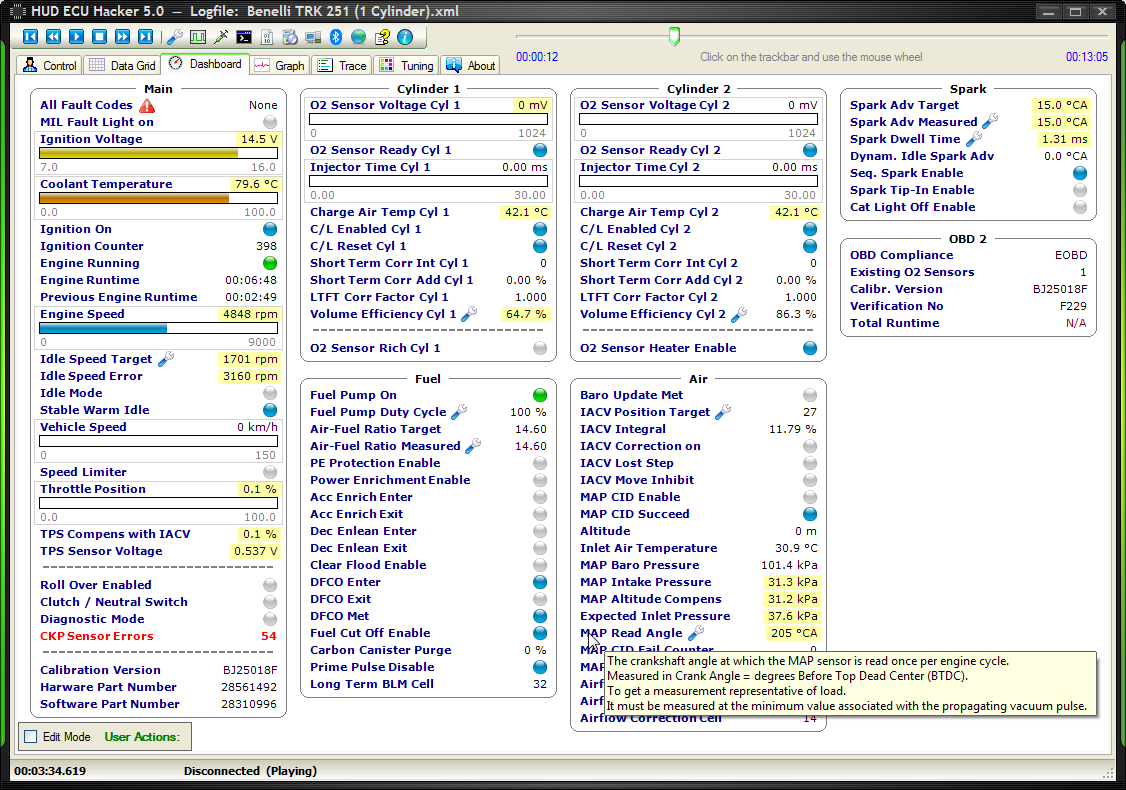
On the left screenshot you see a tooltip which appears when you hover the mouse over a parameter.
Some parameters show a wrench icon. You can click on it and modify these values in the ECU. See Data Slewing.
The dashboard can be configured 100% by the user after checking the checkbox Edit Mode below.
You can create, edit and delete groups and assign parameters to them.
You can move around the groups, change the order of parameters and drag and drop them to another group.
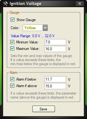
In the dialog on the right you can configure a value parameter.
The ignition voltage has a minimum of 0 Volt and a maximum of 32 Volt.
You can restrict the range of the gauge to something more useful like 7 V to 16 V.
When you set an alarm the parameter will be displayed in red if the value exceeds the given limits.
HUD ECU Hacker - Graph
Show Full Size
Show Full Size
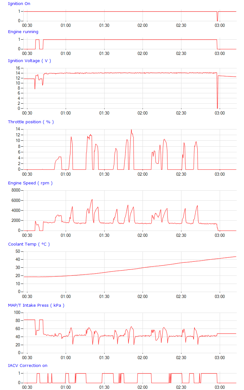
These images are graphs created from the logfile Regal Raptor 350 - Driving.xml
You can chose the parameters that you want to include.
HUD ECU Hacker - Manual Command Injection
Show Full Size
HUD ECU Hacker allows to send commands manually to the ECU and study the response.
For the purpose of hacking you can also enter XX, YY, which will be replaced with all values from 00 to FF.
In the example above entering '21 XX' has sent 256 commands from '21 00' to '21 FF' to the ECU.
Here the ECU (a Delphi MT05) has only answered 4 of the 256 commands, for the others it has returned an error.
Entering '22 XX YY' will send 65536 commands from '22 00 00' to '22 FF FF' to the ECU.
For the CAN Raw protocol you must additionally specify the Tx CAN ID for sending the command and the Rx ID for receiving the response.
Some ECU's send multiple responses on multiple CAN ID's to one command. In this case enter all Rx ID's separated by commas.
Macros
The Injector window supports macros that send commands to the ECU and process complex responses.
int s32_Seed = 256 * u8_Response[0] + u8_Response[1];
etc...
}
</Macro>
...
The function Initialize is executed before starting to poll data.
For all other types of macros you must declare it in the file Macros.xml in a subfolder under 'Macros'.
A macro script must contain at least one public static function that is called when you run the macro.
Each macro function may take any amount of parameters in which user values are passed to the script.
For each script parameter a control (ComboBox, TextBox, CheckBox,...) will be created where the user must enter a value.
The following example shows how a CAN bus communication can be automated with a macro script.
In the XML file you declare the display name, description and the parameters that the user must enter.
Show Full Size
There are different types of macros which support different functions that you can call in your code:
Macro Function
Sniff Terminal
CAN Raw Terminal
ISO 15765 Terminal
RS232 Terminal
Injection Window
Param XML
ECU Emulator
void SendPacket(params Packet[] TxPacks) Sends a CAN Raw packet. Candlelight adapters with ElmüSoft firmware can also send multiple packets in one USB blob.
YES
Only for CAN Raw
Only for CAN Raw
Packet ReceivePacket(int Timeout, bool Throw) Receives a CAN Raw packet.
YES
Only for CAN Raw
Only for CAN Raw
int CalcTxFreeSlots() Calculates how many Tx packets can be sent to a Candlelight adapter before overlow to generate a high busload. See macro 'CAN Bomber'.
YES
Only for CAN Raw
Only for CAN Raw
byte[] SendCommand(int Timeout, params byte[] Payload) Sends a command to the ECU and receives the response.
YES
All except CAN Raw
All except CAN Raw
byte[] SendBusInit(byte[] InitCommand)
Sends a K-Line bus init and then the InitCommand.
Only K-Line
void Disconnect() Disconnects (stop scanning) when the macro has finished.
YES
void OpenCanRaw(int Baudrate, bool b29bit, int CmdID,
                int Filter, int Mask, bool Tx8Bytes)
Opens a new CAN Raw connection.
YES
Packet[] LoadCanLogfile(string Path) Loads a logfile with CAN raw packets. Multiple log formats are auto-detected
YES
bool IsFastPacket(int s32_PGN) returns true if the PGN is an NMEA 2000 Fast Packet PGN
YES
void IdlePolling(int MinInterval) Polls the parameters in the Parameter XML file. (Refresh Dashboard)
YES
string GetParamDisplay(string UID) Gets the display value and unit of a scan parameter in the dashboard.
YES
long GetParamRaw(string UID) Gets the raw value of a scan parameter in the dashboard.
YES
void RefreshParams(params string[] UIDs) Refreshes ReadOnce scan parameter values in the dashboard.
YES
void WritePort(params byte[] Data) Writes bytes to the RS232 port.
YES
byte[] ReadPort(int ByteCount, int Timeout, bool Throw) Reads bytes from the RS232 port.
YES
bool ClearPortRx(bool PrintToTrace) Clears the receive buffer of the RS232 port. Optionally prints the removed bytes in the Rx buffer to trace.
YES
Packet[] OnPacketReceived(Packet RxPack) Generates the ECU reponse(s) for an ECU command that is not defined in the Emulator XML file.
YES
Packet[] GetEmuXmlResponse(string CmdID) Returns the response(s) for CmdID from the Emulator XML file.
YES
void OnSniffData(Packet RxPack) Is called when a packet has been sniffed.
YES
void ChangeKLineBaudrate(int Baudrate) Changes the baudrate for K-Line.
YES
YES
YES
bool UserAborted() Returns true when the user wants to abort the maro.
YES
YES
YES
YES
YES
void PrintTrace(string Text) Prints a text to the Trace pane.
The text can start with "ATTENTION", "WARNING", "IMPORTANT", "ERROR",
"FATAL ERROR" or "SUCCESS" which prints orange / red / green text.
YES
YES
YES
YES
YES
YES
YES
void Sleep(int Interval) Pauses the marco with a precision of 1 millisecond.
If you don't need this precision use Thread.Sleep() instead.
YES
YES
YES
YES
YES
DialogResult MessageBox(String Message,

                                MessageBoxButtons Buttons,

                                MessageBoxIcon Icon)
Shows a messagebox that blocks the macro until a button is clicked.
YES
YES
YES
YES
Macro Function
Sniff Terminal
CAN Raw Terminal
ISO 15765 Terminal
RS232 Terminal
Injection Window
Param XML
ECU Emulator
Apart from these functions HUD ECU Hacker extends the functionality for byte[] arrays.
string Hex = ByteArray.ToHex(int First, int Count) Converts some or all bytes from ByteArray into a hex string "5C A4 CC 9F".
The parameters First and Count are optional.
string Text = ByteArray.ToAscii(int First, int Count) Converts some or all bytes from ByteArray into an ASCII text. Invalid bytes are displayed as '?'.
The parameters First and Count are optional.
byte[] New = ByteArray.Extract(int First, int Count) Extracts some bytes from ByteArray into a new array.
The parameter Count is optional.
byte[] New = ByteArray.Append(byte[] Data, int First, int Count) Appends some or all bytes from the array Data to the bytes in ByteArray.
The parameters First and Count are optional.
byte[] New = ByteArray.ReplaceAt(int Pos, byte[] Replace) Replaces the bytes at position Pos in ByteArray with the bytes in Replace.
bool ByteArray.Matches(params byte[] Data) Returns true if all bytes in both arrays are identical.
bool ByteArray.StartsWith(params byte[] Data) Returns true if the array starts with the bytes in Data.
int ByteArray.Find(int Start, params byte[] Pattern) Returns the position in the array where Pattern was found or -1 if no match.
int ByteArray.DiffBytes(params byte[] Data) Returns the count of bytes that are different in both arrays. Zero means they are identical.
void ByteArray.Fill(byte Value) Fills the entire array with the given byte value.
long ByteArray.ToLong(int Offset, int ByteCount, bool Order_HL) Converts 1 to 8 bytes of the array into a long.
HUD ECU Hacker also extends the functionality for string.
Byte[] Array = String.ParseHex() Converts a String like "11 22 33" into a Byte Array { 0x11, 0x22, 0x33 }.
string StrHex = MyTest.ToHex(2, 3); // here StrHex is "33 44 55"
Please study the existing macro scripts which are full of explaining comments:
Macros\Send Logfile\SendLogfile.cs This script reads the content of a logfile and sends it to the CAN bus.
Macros\CAN Bomber\CanBomber.cs This script sends packets with a fix CAN ID or a range of CAN IDs to CAN bus.
Macros\Honda Sniff\HondaSniff.cs This script for the Sniff Terminal switches the baudrate when a firmware is uploaded to a Honda ECU.
Macros\Deni E1700\E1700.cs This script for the CAN Raw Terminal captures the CAN bus traffic of a DENI software while uploading
calibration tables over a UsbCAN adpater to the E1700 ECU and writes the calibration tables into an XML file.
ECU\MT05\Emulator\Flashing.cs This script for the Emulator automates the upload and download of flash data for the Delphi MT05 / MT05.2.
The heart of the the Delphi MT05 is a 16 bit Infineon processor.
The flash memory in the processor is divided into 4 areas:
The Bootloader is required to start up the ECU.
It will never be overwritten when flashing. This is a protected area.
The Configuration Data will always change when you turn off the ignition key.
The ECU stores non-volatile data here when you turn the ignition key off, like:
fault codes, ignition counter, statistics, fuel learning (BLM), airflow learning and throttle learning.
HUD ECU Hacker does not write into this area, but you can erase the content of this erea. See Reset EEPROM.
The Calibration Tables are used to calculate the optimal operation of the motor depending on
factors like speed, engine load and temperature, etc. They control fuel injection, spark timing, etc.
The Firmware area contains the executable program code.
You should normally not overwrite this area except you know exactly what you are doing.
Additionally you have to buy an USB dongle (30€) which protects their software from piracy.
BitEdit does not support all MT05 versions. Click here for a list of supported calibration versions.
While BitEdit shows 36 tables for the MT05 (in english), ChipTuningPro shows more than 200 tables.
BitEdit is compared with ChipTuningPro like a toy. It has bugs and shows some data and axis wrongly.
3.)
Other tuning software like ECM Titanium is even more expensive (> $1000 USD).
4.)
If you have a MT05 from Kohler or from Briggs & Stratton they sell you diagnostic software that is very restricted.
You are forced to buy their proprietary adapter (> $300 USD) which acts like a dongle.
Each time you start the software, it connects with their server and checks if you have a valid license.
The license is only valid for one year.
As you see clearly: All the tuning and even ECU scanning is a very profitable business. All these companies want your money.
IMPORTANT: A time consuming analysis must be done to get the correct meaning of scalars, tables, maps and their axes.
The companies which sell expensive tuning software do not invest the required time to do this tremendous work.
Doing a real analysis of each and every firmware version of each and every ECU model would result in a price that nobody is willing to pay.
So they enter much of the data by guessing and by copying it from other firmware versions, which results in a lot of wrong information.
Tuning MT05 with HUD ECU Hacker
Download the flash memory of your ECU into a BIN file, go to the tab "Tuning", select your file and HUD ECU Hacker will auto-detect all calibrations.
With the charityware HUD ECU Hacker you save a lot of money by not having to buy commercial software.
Flash download, checksum correction and flash upload of the MT05 can also be done with HUD ECU Hacker.
Please do not forget to give a donation for using HUD ECU Hacker.
An issue with the MT05 is that each ECU firmware version stores the calibration tables at another address in the flash memory.
This means that there is no way to know how many tables exist and where each table starts and where it ends, what the binary data
in the table means, what are the values, meaning and units of the axes and which formula converts the raw table values into display values.
But HUD ECU Hacker analyzes the ECU assembler code and finds automatically 200 calibration tables and 500 scalar values.
It even finds the values and meaning of the axes of nearly all tables and maps by auto detection.
This works with all firmware versions and takes less than one second. The result is 100% reliable.
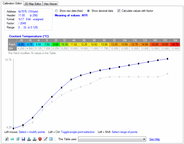
Calibration Editor
Show Full Size
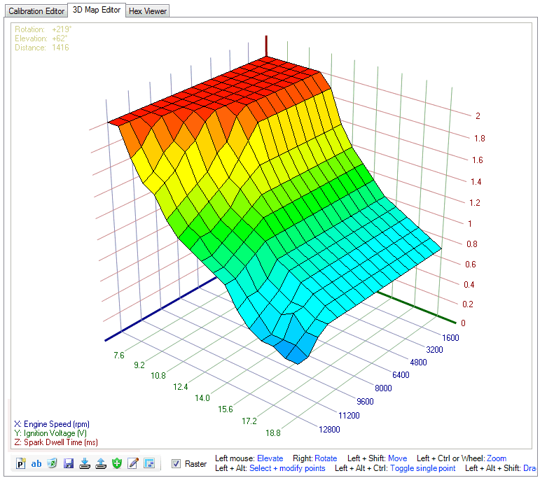
3D Editor
Show Full Size
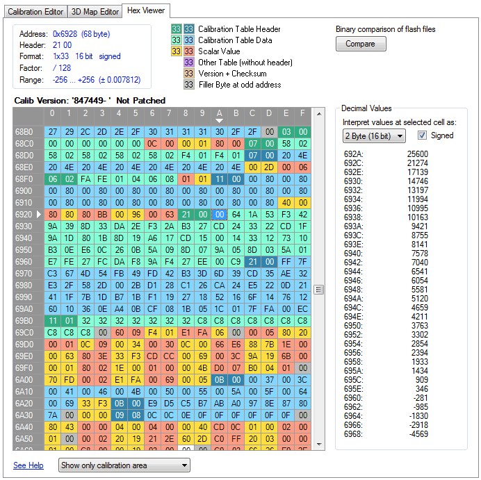
Hex Viewer
Show Full Size
Whenever you load a new flash memory BIN file it will be automatically analyzed and the result is written into a file.
This file has a name like "Firmware_5D06BA79.definitions" and contains the maps, tables, scalars and axes that were found.
The hex number in the filename "5D06BA79" is a CRC (similar to a checksum) of the firmware area in the flash memory.
Each firmware version will generate it's own definition file because each firmware version stores the calibrations at different addresses.
HUD ECU Hacker also detects the count of rows and columns and if the table data is 8 bit or 16 bit and if the data is signed or unsigned.
The auto-detection analyzes the assembler code in the ECU which gives reliable results independent of the firmware version.
The assembler code in the ECU is eternally long (printed on paper it would be one kilometer).
However HUD ECU Hacker does this analysis in less than a second. Here you see a snippet of the huge Delphi code:
c1768e f2 fc f8 f7 mov r12,[0xF7F8]
c17692 f2 fd fc f7 mov r13,[0xF7FC]
c17696 d7 40 01 03 extp #0x301, #1
c1769a f2 fe 22 29 mov r14,[0x2922]
c1769e da c1 f8 14 calls FUN_c114f8
c176a2 f0 c4 mov r12,r4
c176a4 f6 fc f8 f7 mov [0xF7F8],r12
c176a8 f2 fd fc f7 mov r13,[0xF7FC]
c176ac 42 fd f8 f7 cmp r13,[0xF7F8]
c176b0 fd 08 jmpr cc_ULE,LAB_c176c2
c176b2 22 fd f8 f7 sub r13,[0xF7F8]
c176b6 f6 fd f6 f7 mov [0xF7F6],r13
c176ba e1 12 movb RL1,#0x1
c176bc f7 f2 e6 f7 movb [0xF7E6],RL1
c176c0 0d 08 jmpr cc_UC,LAB_c176d2
As you see, assembler code is extremely cryptic. I spend several weeks in understanding what the ECU does internally.
I hope that you honor this tremendous work and be so honest to respect the charityware policy of HUD ECU Hacker.
Hex Viewer
The Hex Viewer shows how scalars, tables and maps are lined up in the calibration area of the flash memory.
Reverse Lookup tables appear with bold text.
Axis values are calculated by a formula. The parameters for the formula are not stored in the calibration area.
You will see mostly two white areas of approx 30 bytes at the beginning of the calibration area.
All white areas contain tables which are never used by the firmware or they are filled with zeroes.
These tables are orphans. They contain data, that may be used in other firmware versions.
There are other tables which don't have a header, so the length and type of data cannot be auto-detected.
They appear purple in the Hex Viewer.
The Hex Viewer can also compare two BIN files and show the differences.
Delphi Calibration Data
Please read this chapter in the help file.
Completing Auto-Detection Results
Please read this chapter in the help file.
Editing Calibrations
Please read this chapter in the help file.
Working with Patches
Please read this chapter in the help file.
Dyno Tuning with Wideband Sensor
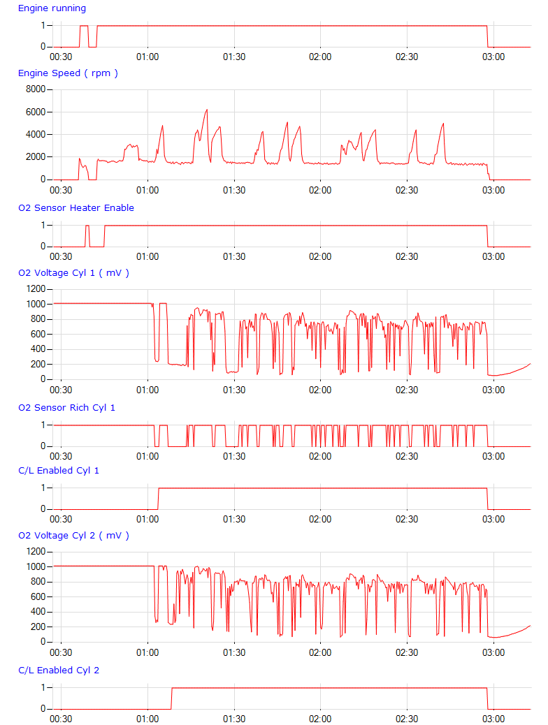
HUD ECU Hacker supports to record ECU parameters together with an external wideband O2 sensor.
Additionaly you need any Arduino or Teensy board that transmits the wideband sensor voltage over USB to HUD EU Hacker.
The cheapest is the Arduino UNO for $3 on AliExpress. It has 6 analog inputs for 0V to 5V.
Dyno Tuning does not require the Delphi MT05.2, it is available for any OBD2 compliant ECU.
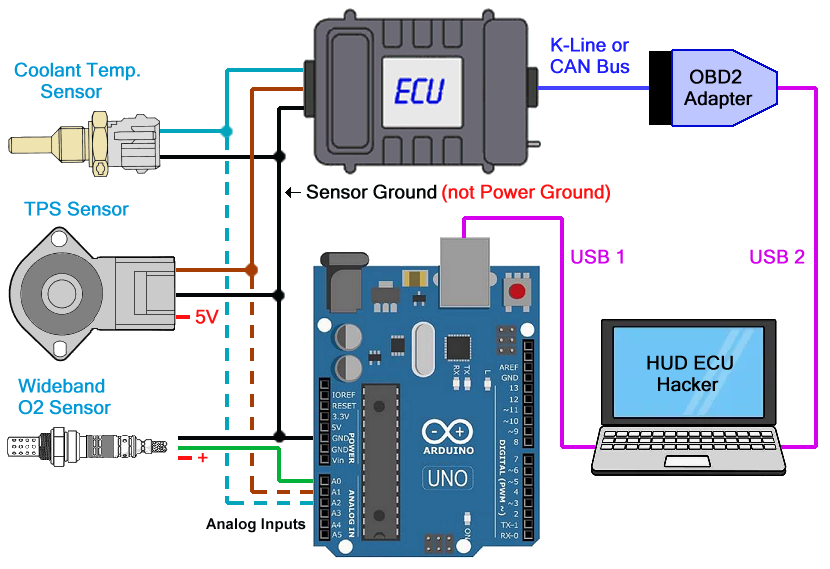
Connection Diagram
Show Full Size
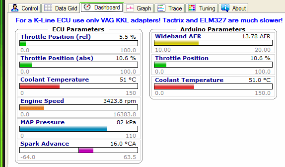
Dashboard Parameters
Show Full Size
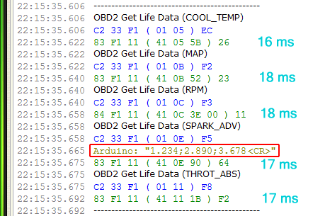
K-Line Scan Speed
Show Full Size
Temp. Sensor
Show Full Size
Create your copy of the Parameter XML file ...\ECU\Dyno Tuning\Parameters\Dyno Tuning.xml.
The original file will be overwritten when you update HUD ECU Hacker the next time.
Change the ECU Model in your file to the name of the motorbike that you are tuning:
In HUD ECU Hacker click the green Reload button and select the ECU Model with your new name.
When you click Connect HUD ECU Hacker automatically searches the CAN bus or K-Line protocol on which the ECU responds.
It sends the OBD2 PIDs 01 05 (Coolant Temperature), 01 0B (MAP pressure), 01 0C (RPM), 01 11 (Throttle) and optionally more.
If you want to increase the scanning speed of a slow K-Line ECU, you can transmit TPS and Temperature through the Arduino.
The more OBD2 parameters you disable in the Parameter XML file, the faster becomes the scanning speed.
You find the Arduino Script in subfolder ...\ECU\Dyno Tuning\Arduino\Arduino.ino
It has been tested on the Arduino UNO, but it can also be used for any other Arduino board. Read the comments in the script!
Install the Arduino IDE and in menu Tools select the Board and the Port.
Then compile and upload the script to the processor by clicking the right arrow button.
After the Arduino has been programmed the LED on the board must blink once per second, otherwise something is wrong.
The Arduino sends every 25 ms data like "1.234;2.890;3.678\r" which contains the 3 voltages of the analog inputs A0, A1, A2.
You can modify the script to send more or less voltages.
Open the COM port with 115200 baud in ASCII mode in the RS232 Terminal and verify that you receive the Arduino data.
Enter the Arduino Port into your Parameter XML file and check the formulas to convert voltage into display value.
The formula for ARDUINO_AFR converts the 0 to 5 Volt from the wideband O2 sensor into the AFR range from 10 to 20.
The parameter ARDUINO_TPS is only needed if you want to transfer TPS through the Arduino.
It converts 0 to 5 Volt into the absolute throttle position 0% to 100%.
To calculate the relative throttle position you need the Arduino voltages at minimum and maximum position.
For example if the released throttle delivers 0.7 Volt and the WOT voltage is 4.5 Volt the formula becomes:
"100 * ($Val - 0.7) / (4.5 - 0.7)"
The result will be a display of 0% at 0.7 Volt and 100% at 4.5 Volt.
The parameter ARDUINO_TEMP is only needed if you want to transfer the coolant temperature through the Arduino.
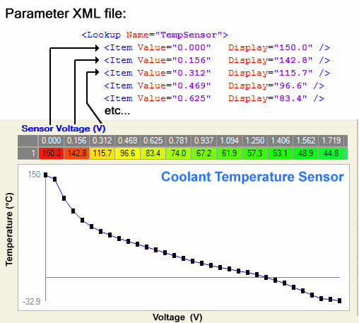
As temperature sensors are not linear you must enter a lookup table to convert voltage into temperature. (See screenshot)
For the Delphi MT05 you find these values in the calibration Input / Output System --> Coolant Temp Sensor.
After verifying that the Arduino parametes show the same values as the ECU parameters you can disable the OBD2 commands.
With these settings you have optimized the scanning speed of a slow K-Line ECU to the maximum.
AFR, TPS and Temperature are transmitted by the Arduino every 25 ms.
MAP and RPM are transmitted every 35 ms by the ECU (each K-Line command needs approx 17 ms). (See screenshot)
If you connect to the ECU over the fast CAN bus you don't need to disable parameters to increase the scanning speed.
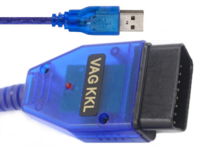
IMPORTANT: If you want the maximum scanning speed over K-Line you MUST use a VAG KKL or VAG K+CAN adapter!
Tactrix adapters are significantly slower and ELM327 adapters are crap.
IMPORTANT: All ECUs have a pin for Power Ground and another pin for Sensor Ground.
If you connect to the Power Ground instead of the Sensor Ground you will measure garbage voltages!
Adapting to other ECU's
HUD ECU Hacker can be adapted to scan any ECU which uses the KW 1281 / ISO 9141 / ISO 14230 / CAN Raw / ISO 15765 protocol.
This is a process in 5 steps.
You need the ECU and a scantool or software from the vendor which understands the vendor specific ECU data.
The traffic between ECU and scantool must be captured and reverse engineered. Doing this is not illegal.
IMPORTANT: A Universal OBD2 Scantool which only shows OBD2 data is useless. HUD ECU Hacker can already display OBD2 data.
The OBD2 standard has been designed to verify that a vehicle complies the emission laws.
OBD2 gives very limited information because the manufacturers implement only few commands, just the minimum to fulfil the law.
OBD2 may only show you Vehicle Speed, Engine Speed, Coolant Temperature, O2 Sensor and Throttle Position, and that's it.
Generally ECU's can report much more details to the service technician, but in a proprietary and secret data format of the manufacturer.
Only an expensive scantool or software from the ECU vendor may give you this information, but not a "universal" OBD2 scantool for all vehicles.
For example for the Delphi MT05 the vendor specific command 30 allows data slewing.
And the vendor specific command 21 returns details like crankshaft errors, stepper motor position, block learning (BLM) and much more.
These details (90 scan parameters) can not be obtained with a "universal" OBD2 scantool or OBD2 computer software.
The response of command 21 01 is a proprietary and undocumented data packet from Delphi.
I obtained the meaning of this 100 byte packet by analyzing the ancient PCHUD software.
You can do the same for any other ECU if you have a scantool or software which shows these details.
Step 1a. Sniff Data internally
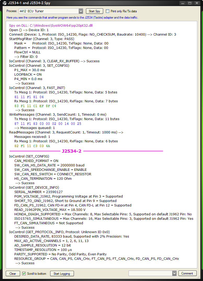
If you want to sniff a Tuning software on Windows that uses a J2534 adpater, like Tactrix, you can do that easily with the J2534 Spy.
Otherwise follow Step 1b.
Step 1b. Sniff Data externally
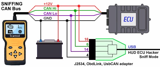
When you enable the checkbox 'Sniff Mode' you can capture the traffic between the ECU and a scantool / OBD software.
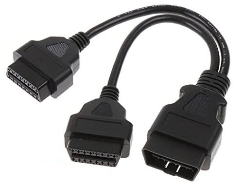
Connecting an additional sniff adapter over a splitter cable to the K-Line will mostly not work.
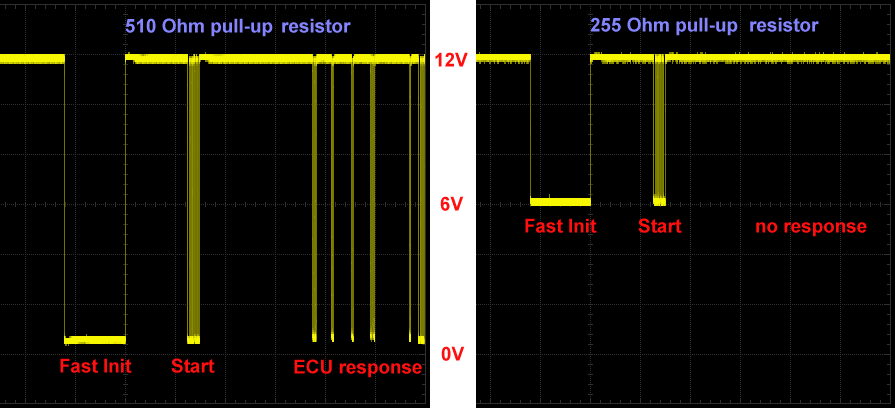
The reason is that each adapter has a pull-up resistor (mostly 510 Ω) between K-Line and +12V.
When you connect 2 adapters the parallel pull-up resistor becomes 255 Ω.
Adapters and ECU have a current limitation to protect them from shortcuts.
Most adapters don't provide enough current (50 mA) to pull K-Line to ground over 255 Ω.
Depending on the pull-up resistor and the current limitation you will not capture anything or the scantool stops working.
Here you see the result of connecting two adapters at the same time. The voltage does not reach 0V anymore.
Show Full Size
Show Full Size
It may also happen that you can sniff data as long as the motor is off.
But when the motor runs the battery voltage rises to 15V and now you don't capture data anymore or get crippled data.
The higher the battery voltage the more current is required to pull K-Line to ground.
However, there are also adapters with an internal pull up resistor of 1 kΩ. They may function unchanged.
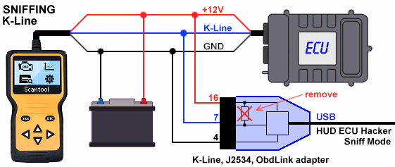
The only bullet-proof solution is to modify an adapter and remove the SMD pull-up resistor between pin 7 and 16.
You can either convert an adapter into a sniff adapter by removing this resistor completely
or you can insert a switch into the adapter which allows to chose between normal mode and sniff mode.
K-Line
Show Full Size
CAN Bus
Show Full Size
No modification in the adapter is required for CAN bus sniffing.
The J2534 and OBDLink adapters require 4 pins to be connected.
If you use a UsbCAN adapter only 2 pins must be connected: CAN0H and CAN0L.
Store the sniffed data into a logfile by clicking the button 'Start Logging' in the Trace pane.
Navigate through all menus of the scantool to capture all commands.
IMPORTANT: If the logfile has many "Invalid Data" you have the wrong baudrate or the wrong protocol.
Step 2. Test the ECU Emulator
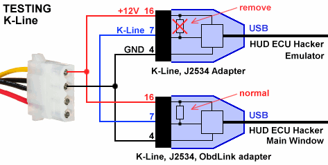
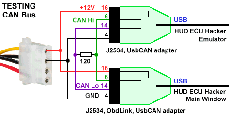
Connect HUD ECU Hacker to it's own Emulator to learn how to use it.
You can use a battery or the 12 Volt from a cheap computer power supply (yellow wire).
ATTENTION:
ELM327 / OBDLink adapters do not have the functionality required for the emulator.
J2534 adapters will not work with any protocol that uses the 5-baud initialization.
Use a K-Line adapter for K-Line Emulation.
For CAN Bus an additional 100 Ω or 120 Ω resistor between CAN Hi and CAN Lo is indispensable because adapters do not have it built-in.
K-Line
Show Full Size
CAN Bus
Show Full Size
To test K-Line select ECU model "Delphi MT05.2" in the emulator and in the main window.
To test CAN bus select ECU model "Autodetect ...." in the emulator and with button 'Configure' switch to ISO 15765.
Then in the Emulator window click "Open", then in the main window click "Connect".
Now you should see the data coming from the emulated ECU in the dashboard.
Change the values of command 21 01 or 22 21 01 in the emulator and study their effect on the display in the dashboard.
Step 3. Simulate the ECU
Please read this chapter in the help file.
Step 4. Enter the XML Commands and Parameters
Please read this chapter in the help file.
Step 5. Enter the XML Names and Descriptions
Please read this chapter in the help file.
Download and Installation
Program
Version
Date
Size
HUD ECU Hacker
6.1
2.oct.2026
28.9 MB
Windows may block the installer in the downloaded ZIP file because it has no digital certificate.
Please right click the ZIP file, select 'Properties' and check 'Unblock'.
You need the .NET framework 4.0 or higher.
On Windows 10 and 11 this is already installed.
Install USB Drivers
In the toolbar at the top you can then install the drivers.
Click the toolbar button Device Manager to see if there are yellow exclamation marks which indicate a missing driver.
The toolbar has a tooltip for each button which appears when you hover the mouse over it.
Show Full Size
Trouble Shooting
If your ECU is not listed under "ECU Model" connect with "Autodetect OBD2" which tries multiple protocols, init modes and ECU addresses.
All newer ECUs will respond to OBD2 commands.
Errors when connecting to the ECU:
The ignition key must be on.
The kill switch must be in the position where it allows the motor to run.
Some motorbikes (Benelli) require the side stand to be up otherwise the ECU will not respond.
It is not necessary to start the motor to establish a connection.
Check that you have connected the three wires correctly as shown in the connector diagram.
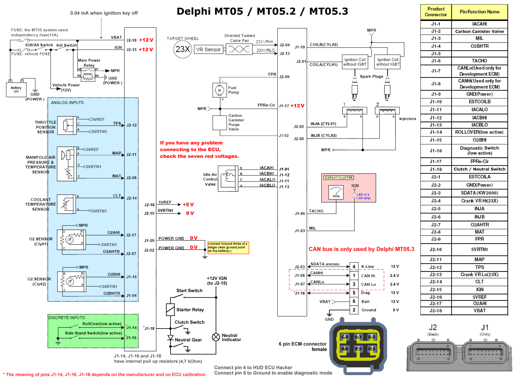
If you have a MT05 ECU verify that the seven voltages are correct that are marked red in the MT05 diagram.
The voltage at the K-Line wire MUST be +12 Volt while the adapter is connected to the ECU.
Some adapters do not enable the pull up resistor when they are in power safe mode.
Measure the voltage while clicking the "Connect" button in HUD ECU Hacker which will activate the adapter.
If you use a K-Line or J2534 adapter ecxecute the Echo Test to check the adapter.
There are 2 types of timeout errors which indicate different errors:
Timeout waiting for echo means always that you have a hardware problem or the wrong COM port.
Timeout waiting for response (or received garbage characters) with ELM327 adapter may mean that the baudrate is wrong.
You can change the baudrate in the window "Configure Adapter". Normally ELM327 adapters use 38400 baud or 115200 baud.
Timeout waiting for response with K-Line / VAG adapter may happen rarely.
The reason is that the ISO 14230 protocol is very time critical. It demands 50 ±1 ms for the fast init.
But Windows as a multitasking OS is not very precise and the interval seen on an oscilloscope may vary from 45 ms up to 70 ms.
If the interval between fast init and the command 'Start Communication' exceeds the limits the ECU does not respond.
K-Line adapters are the only adapters where timing depends on the computer. J2534 and ELM327 adapters create a precise timing.
If you get this type of timeout error, try the following:
Click 'Connect' several times until it works. It may work 8 of 10 times.
Some adapters (e.g. some SiliconLabs chips) do not support the way how HUD ECU normally generates the fast init pulse.
Try switching Fast Init Mode 1 / Fast Init Mode 2 in the window "Configure Adapter".
For slow computers you can enter in the same window a K-Line timing correction which is added to the 50 ms interval:
ATTENTION: If you enter an invalid value here you may screw up the fast initialization forever.
If changing this value did not solve your problem, reset the correction to zero otherwise you may never be able to connect.
To verify the timing you need a digital oscilloscope, otherwise it is pure try and error.
BUSINIT: ERROR from an ELM327 adapter means that the adapter did not receive a valid response from the ECU.
You can also change the configuration in "Autodetect OBD2.xml". Some older ECU's use 9600 baud.
If you have tried everything and the ECU still does not respond, test your adapter: Connect HUD ECU Hacker to it's own emulator.
Therefore you need a second adapter. See Emulator
If you have any problem you can send me a Trace logfile with the error message.
Do not send me screenshots from the Trace pane or even screen photos!
You find my email below at the end of the page.
But first try all the steps above.
Appendix
Delphi MT05.3
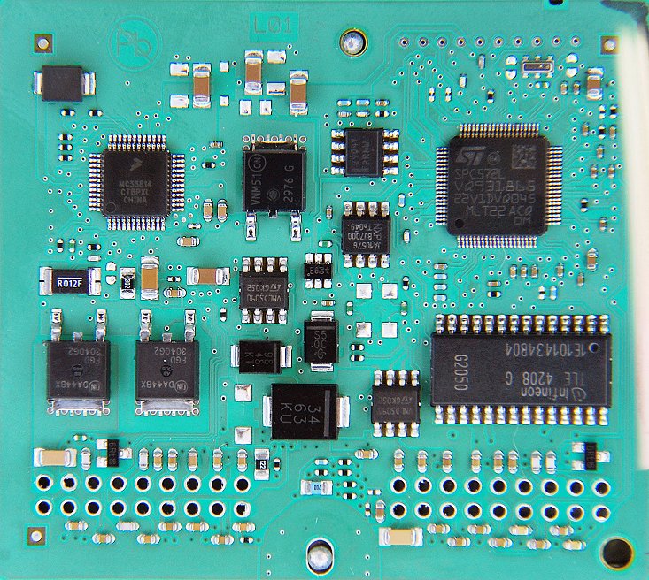
The new Delphi ECU is the MT05.3 which is Euro 5 compliant and uses CAN bus.
This ECU is a complely new development, using a modern 32 bit processor: SPC 572L.
The consequence is that all my endless work for flashing the MT05 / MT05.2 is completely useless now for the MT05.3
May be some day in the future I will add support for flashing the MT05.3.
But this is the hard work of another entire year.
HiSun MT05
HiSun makes a proprietary ECU with another 32 bit processor: FS32K144.
But it supports the same commands for scanning as the Delphi MT05.3 over CAN bus.
Delphi MT05.3
Show Full Size
HiSun MT05
Show Full Size
Rongmao MT05 and RM08
Rongmao uses the same case and plugs as the Delphi MT05.
It also sends the same scan parameters, so it can be scanned with HUD ECU Hacker.
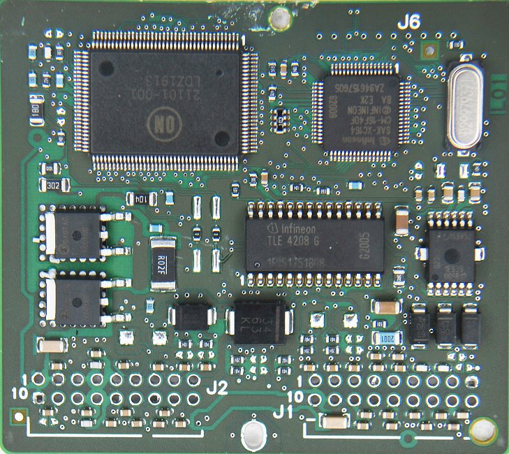
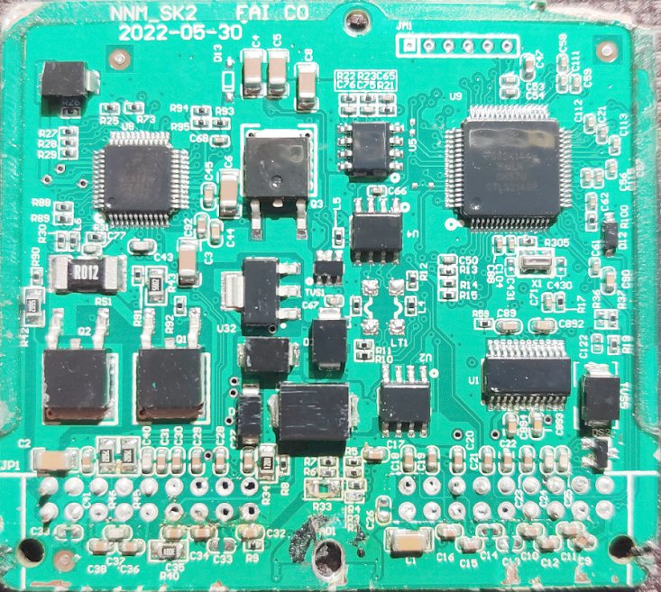
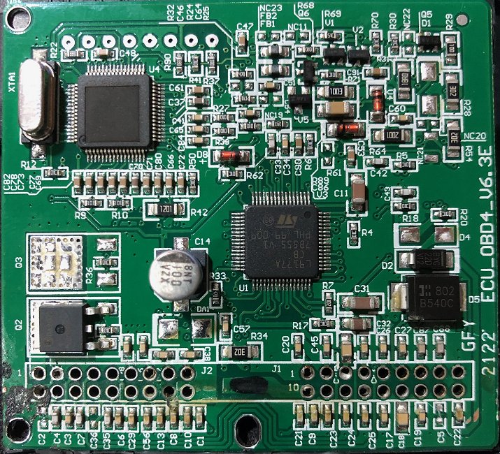
But inside is a different board with different chips. (see photo below)
The PCB boards of the Rongmao MT05 and RM08 are identical.
Rongmao has milled away the processor label, so the processor model is hidden.
But I know that the Rongmao processor is an Infineon SAK-XC2365B-40F80LR with 320 kB flash memory.
However, flashing is not possible because Rongmao uses their own commands and even a proprietary protocol for flashing.
Harley Davidson MT05
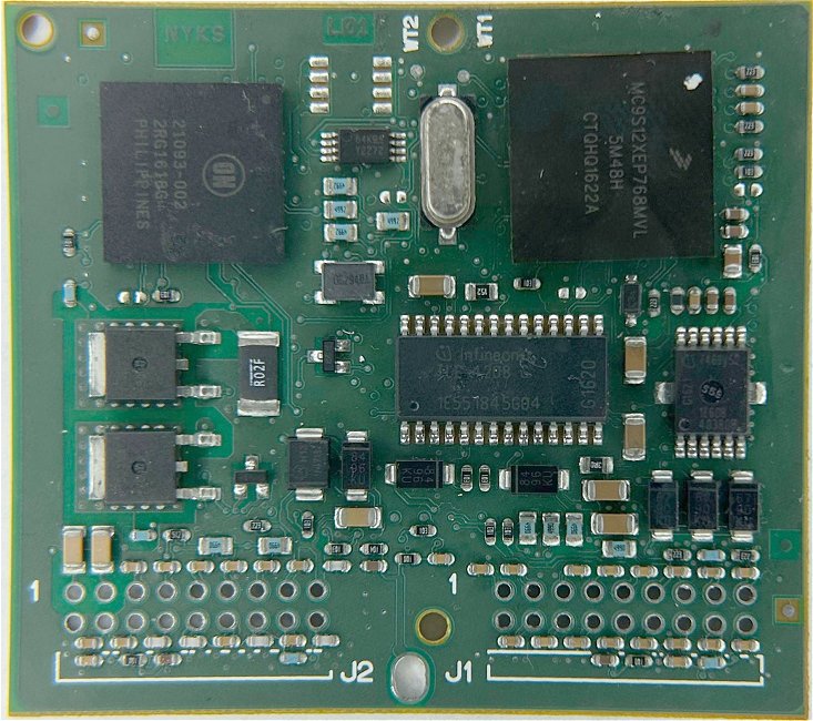
Also Harley Davidson uses an ECU which looks from the outside like the Delphi MT05.
But inside is another processor (MC9S12XEP) and obviously another firmware with different calibations.
This ECU cannot be flashed with HUD ECU Hacker because it is completely different.
It only supports CAN bus and even the ECU pins are connected differently. See Manual
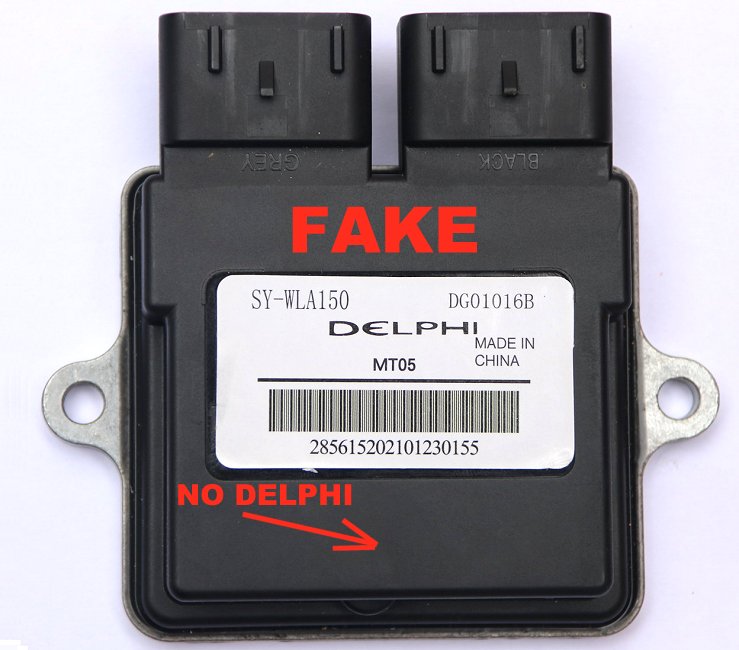
Chinese fake clones of the MT05 or MT05.2 have appeared in the market which are garbage.
They are full of bugs and only the very basic OBD2 commands are implemented.
These ECU's are so extremely buggy that they are not even able to send a correctly formatted DTC response!
Detailed scan data is not available, Data Slewing and flashing are not possible.
There are even fake MT05 which respond only on CAN bus instead of K-Line. (The real MT05 / MT05.2 does not respond on CAN bus)
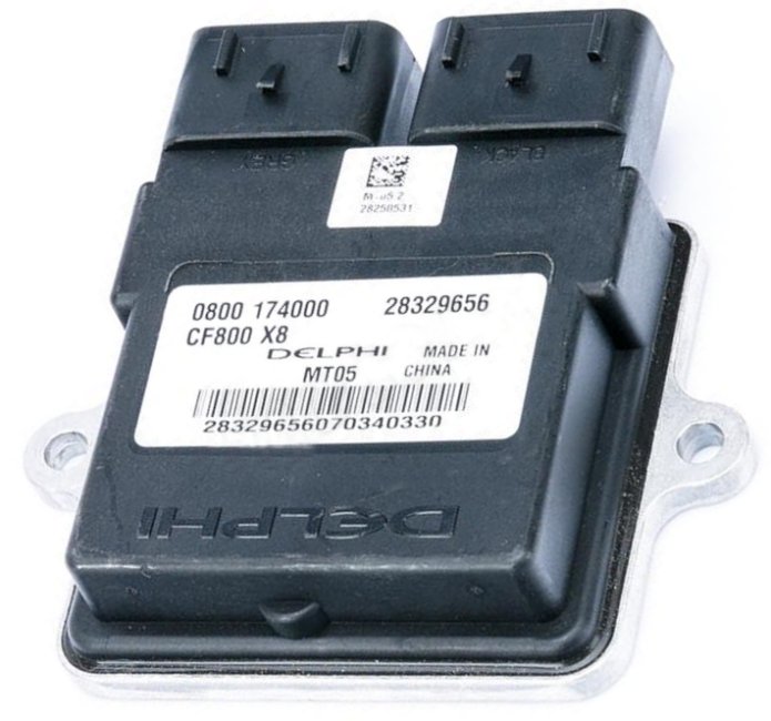
An ECU is only a Delphi MT05 if it has the SAK-XC164CM-16 processor from Infineon inside.
An ECU is only a Delphi MT05.2 if it has the SAK-XC164CS-32 processor.
An ECU with any other processor that says "Delphi MT05" on the label is a fake.
Real Delphi MT05
Show Full Size
Fake Delphi MT05
Show Full Size
On the real ECU's you see that "DELPHI" is engraved in the plastic of the cover. The fake does not have this.
HUD ECU Hacker will detect when you have connected a fake ECU and show an error message.
Chinese MT05 Clones
ATTENTION: There are also Chinese MT05 clones. These are not fake. They are an exact copy of the original Delphi ECU.
A clone has the same processor as the orignal, so it can even be flashed with HUD ECU Hacker.
Overheating Risk
A big problem of all combustion motors is overheating. If cooling fails, the motor will be damaged.
A water cooled motor will reach 80 degree Celsius, max 95 degree.
If the motor is air cooled the temperature may reach 140 degree.
The first damaged part will be the cylinder head gasket. As a result coolant will enter into the cylinders and vaporize.
You will lose coolant through the exaust pipe. A vicious circle accelerating the damage.
Replacing the gasket is expensive because the motor must be opened.
If you drive longer with an overheated motor the cylinders will be ruined and you need a new motor.
The cause of overheating is a failure in the cooling system. This may be due to a defective ventilator or lack of coolant.
Some motorbikes (like my Regal Raptor) neither have a temperature display nor an overheating lamp.
This is a severe problem because the owner has no chance to check the temperature of the motor.
ATTENTION: The Delphi MT05 is so stupidly programmed that it does NOT protect the motor from overheating!
Although the ECU has a temperature sensor and knows the exact temperature, it will not turn the motor off when it becomes too hot.
The MIL/EFI light may turn on when it is already too late (Error P0117 at approx 200 degree) or it never turns on.
Check regularly if your motorbike has sufficient coolant! Use HUD ECU Hacker to check the current temperature.
If coolant disappears within a few days or weeks without a leak your motor is probably already damaged.
IACV Calibration
The IACV (Idle Air Control Valve) is like a bypass for the throttle valve.
It allows a small amount of air to enter into the engine while the throttle is closed.
If the IACV does not work correctly you may have the following problems:
The engine cannot be started
The engine goes off alone while running idle (especially when it is cold)
The idle speed is irregular
The ECU may generate fault code P0505.
The IACV has a stepper motor which moves a pintle precisely to a position between 0 and 255.
Position 0
Position 255
To maintain the stepper motor in the desired position a current must flow permanently which generates a magnetic field.
Therefore the stepper motor becomes warm although it does not move.
Position 0: The valve is fully closed. Air can only enter through the throttle into the intake manifold.
Position 168: The valve is in the parking position for the next cranking. (Defined in the calibration IAC Park Position).
Position 200: The maximum position that the ECU will use. (Defined in the calibration IAC Position Max).
Position 255: The valve is fully open.
You can use the Data Slewing window to test the IACV while the engine runs.
If you enter a delta value of +30 steps, more air enters and you notice that the idle speed increases.
If you enter a delta value of -30 steps, less air enters, the idle speed decreases and the engine may stall.
Aprox 5 seconds after turning the ignition key off the ECU parks the IACV and stores the pintle position in flash memory.
The IACV has no sensor which reports the current mechanical position to the ECU.
The ECU simply trusts that the position stored in the flash memory is the same as the real mechanical position.
But the range which the stepper motor can move is wider than the programmable range from 0 to 255.
So if the ECU loses synchronisation with the mechanical position you will have one of the problems listed above.
I found the following way to calibrate the IACV (while the engine is off) with the older MT05 ECU.
Take the IACV out so you can see the pintle position.
Connect HUD ECU Hacker.
In the Data Slewing window move the IACV to the absolute position 255.
Now disconnect the battery so the ECU cannot store this position in the flash memory.
Reconnect the battery. You should hear the fuel pump running. Now the ECU assumes the IACV in parking position.
Repeat steps 2 to 5 until the pintle does not move anymore. The spring must be completely compressed.
Now you have the pintle in the real mechanical position 255.
In the Data Slewing window click Reset all presets in ECU which moves the pintle to the parking position.
Turn off the ignition key. Now the ECU stores the correct parking position in flash memory.
Mount the IACV back into it's place.
When driving the next time the airflow self-learnig will adapt to the new conditions.
The newer MT05.2 already has the EEPROM Reset, which also adjusts the IACV, but in a different way.
The ICAV must be mounted in the throttle body while executing the EEPROM Reset.
The ECU will move the stepper motor until the pintle is mechanically blocked when the IACV is fully closed.
This will be the new position 0.
Play the logfile Regal Raptor 350 - IACV Idle Warmup.xml and create a graph with the preset IACV and Idle.
Here you see how the MT05 slowly adjusts the IACV during a 12 minute idle warm-up from 18 °C to 80 °C:
Self Learning
The ECU adapts to changing load, atmospheric pressure and fuel quality to keep the emissions at a minimum while running in closed loop.
It also compensates a worn out fuel pump or a dirty air filter.
Based on the O2 sensor feedback, the short term adaption increases (> 0) or decreases (< 0) the amount of fuel to get the optimal air/fuel mix.
If the short term adaption (Integrator) deviates too much, the long term adaption will be adjusted.
The long term fuel adjustment is stored in a table which contains Block Learn Multipliers (BLM).
Multipliers have values between 0.0 and 2.0 where values > 1.0 mean more fuel and values < 1.0 mean less fuel.
The Delphi MT05 uses a table with 36 cells (16 bit) for each cylinder which is stored in the flash memory.
MAP
TPS
< 1900
< 2800
< 3750
< 4500
< 5800
< 7200
< 9000
> 9000 rpm
< 30 kPa
< 4 %
Cell 0
Cell 1
Cell 2
Cell 3
Cell 4
Cell 5
Cell 6
Cell 7
< 46 kPa
< 10 %
Cell 8
Cell 9
Cell 10
Cell 11
Cell 12
Cell 13
Cell 14
Cell 15
< 62 kPa
< 19 %
Cell 16
Cell 17
Cell 18
Cell 19
Cell 20
Cell 21
Cell 22
Cell 23
> 62 kPa
> 19 %
Cell 24
Cell 25
Cell 26
Cell 27
Cell 28
Cell 29
Cell 30
Cell 31
Rolling Idle Cells
Cell 32
Cell 33
Cell 34
Cell 35
The X and Y axis values come from the lookup tables 'BLM MAP Boundary', 'BLM TPS Boundary', and 'BLM RPM Boundary'.
The Y axis may be based on MAP compensated pressure or throttle position. This is defined by scalar 'BLM Load Option'.
The rolling idle cells are used when the engine is idling.
While the engine is running you see in the dashboard which cell the ECU is currently using and what is the value of this cell:
This capture is from logfile 'Regal Raptor 350 - Driving.xml' at 01:16:246
A long term correction factor of 1.015 means adding 1.5% more fuel.
The ECU also learns automatically which voltage of the throttle sensor corresponds to 0% throttle position (TPS auto-zero).
Reset EEPROM (NVRAM)
If some BLM cells reach the minimum or maximum adaption limit, the fault codes P0171 or P0172 will be generated.
These errors mean that there is a defect (IACV, injector, fuel pump, air filter) which the ECU cannot correct anymore.
If you get these errors you must reset the self learning data in the configuration area with the button Reset EEPROM which will:
Erase the fuel self-learning data (BLM Table). All correction factors will be reset to 1.0 (no correction).
Erase the airflow self-learning data (Airflow Table). All correction factors will be reset to 1.0 (no correction).
Erase the throttle self-learning data (Auto-Zero). The throttle zero will be set to the default in the scalar 'TPS Raw Intercept'.
Erase all statistics. This will reset all time counters (except total runtime), max temperature, max batt voltage, max speed,...
Erase all historic DTC fault codes
Reset the IACV pintle position
ATTENTION: If you do not repair the underlying hardware defect the errors P0171 / P0172 will come back soon.
You need the EEPROM reset also after replacing the throttle sensor.
After erasing the configuration data the ECU will write fresh data the next time you turn the ignition key off.
Some older MT05 firmware versions do not implement the command which HUD ECU Hacker uses when you click the button Reset EEPROM.
In this case you may have luck trying one of the following two options:
Turn the ignition key off while pin 5 of the ECM plug is connected to ground (pin 2), then wait 10 seconds.
This will only work if the scalar 'J1-16 Input Usage' is 1.
Or turn the ignition key off, wait 10 seconds, turn the key 5 times on/off within 5 seconds, then (while off) wait another 10 seconds.
This will only work if the scalar 'J1-16 Input Usage' is not 1.
Rescue a bricked MT05
If you have uploaded a wrong flash file or interrupted the upload you may have 'bricked' your ECU.
A 'bricked' ECU will neither allow to start the motor nor will it respond on K-Line.
'Bricked' means that your ECU is now as useful as a brick. Congratulations!
In this case you have to switch the ECU into 'bootloader mode' and then you can connect again.
Unplug the plugs J1 and J2 and connect the ECU only to the battery and the K-Line or J2534 or ELM327 adapter:
Show Full Size
You need one jumper between pins 10 and 17 and another jumper between pins 11 and 16.
This switches the ECU into 'bootloader mode' and allows to upload a valid flash file.
Additionally you connect +12V to pins 15 and 18, Ground to pin 2 and K-Line to pin 3.
The first 16 kB of the flash memory contain the bootloader.
This memory area will never be overwritten when you upload a flash file.
This assures that the bootloader stays always intact even when flashing goes wrong.
Crankshaft Position Sensor
The crankshaft position sensor reports the exact position of the crankshaft to the ECU.
The ECU needs this to calculate the moment of spark generation and of measuring the Intake Air Pressure sensor.
On the crankshaft there is a flywheel with teeth every 15 degree. Each tooth induces a pulse in a fixed pick up coil.
There are 24 positions on the 360 degree rotation. One of them is missing, so there are 23 pulses per rotation.
The gap from the missing tooth indicates the position near BDC (Bottom Dead Center) of cylinder 1.
Example: The motor runs with 1500 rpm. This is 1500 / 60 = 25 rotations per second = 40 ms per rotation.
This oscilloscope capture measured at ECU pin J2-04 shows the 25 * 23 = 575 pulses/second.
Show Full Size
The faster the motor runs the higher becomes the voltage.
The logfile Benelli TRK 251 (1 Cylinder).xml shows several CKP Sensor Errors which are increasing with the time.
But they are still not enough to turn the MIL/EFI indicator light on.
Battery
Lead-Acid batteries allow to easily detect their charge status by simply measuring the voltage while the ignition key is off.
At 12.8 Volt it is completely full.
Very detailed information about batteries can be found at the Battery University.
The lifetime of a motorbike battery is approx one year when used frequently.
When the voltage of the fully charged battery drops below 9 Volt while cranking the battery should be replaced.
If the alternator / generator works correctly the voltage should be between 13.5 and 14.5 Volt while the engine is running.
If the regulator is defective and the voltage rises to more than 15 Volt the battery will be damaged.
Plugin for Bosch PSG 5 (Injection Pump)
This ECU is used in the Bosch fuel pump VP44 in cars and vans from Volkswagen, Opel, Audi, Nissan, Ford, BMW and MAN.
The PSG5 controls the injection of fuel into the cylinders and communicates with the main ECU over CAN bus.
Additionally it allows diagnostic over K-Line which is used for scanning and the additional operations.
Store the angles dPhi and Phi1 either in RAM for testing or in EEPROM
Read ROM
K-Line
Read the entire ROM of the processor
Read EEPROM
K-Line
Read the EEPROM in the ECU
Read RAM
K-Line
Read the RAM of the processor
Write EEPROM
K-Line
Write the EEPROM
Write RAM
K-Line
Write the RAM
Read OEM blocks
K-Line
Read the 4 OEM blocks in the protected area of the EEPROM
Write OEM blocks
K-Line
Write the 4 OEM blocks in the protected area of the EEPROM
Display Pins
K-Line
Display the configuration and status of all processor I/O pins
Set Pins
K-Line
Set the status of a processor I/O pin
Analyze CAN bus Chip
K-Line
Display configuration and errors of the CAN bus chip in the ECU
Reset Ford Immo Key
CAN Bus (and K-Line)
Reset the Ford Immo key after replacing the PSG5 or the main ECU
Set Ford Immo Key
CAN Bus
This is only for testing on the desk
Connection
K-Line: All operations over K-Line require a VAG KKL or VAG K+CAN adapter because
the old KW 1281 protocol is neither supported by J2534 (Tactrix) adapters nor ELM327 / OBDLink adapters.
The operation Reset Ford Immo key is executed over CAN bus.
But Bosch has programmed a stupid delay of 10 minutes that you have to wait before the key can be reset.
If you only have a CAN bus connection to the PSG5 you have to wait 10 minutes.
But if you connect additionally a K-Line adapter, HUD ECU Hacker will abbreviate this interval to 2 seconds.
To avoid that you have to connect two adapters at the same time it is recommended to use a VAG K+CAN adapter
and HUD ECU Hacker will automatically switch the adapter between CAN bus and K-Line.
Therefore you must select adapter "VAG K+CAN" and click "Connect" before executing the plugin operation.
Fast Reset Ford Immo Key
Show Full Size
Details about the operations
To get a detailed description select ECU model Bosch PSG 5 and hover the mouse over the bulb icon:
Purchasing the PSG 5 Plugin
There is no documentation about the K-Line or CAN bus commands of this ECU anywhere in internet.
All the PSG 5 functionality in HUD ECU Hacker is based on a very difficult and very time consuming reverese engineering.
The scanning of this ECU has been implemented without charge for you.
But the above operations required a reverese engineering of the ECU hardware and firmware which took 8 months, working full time!
Therefore this additional functionality is available only after purchasing a plugin for the Bosch PSG5.
To see more details about the purchase please click the button Load Plugin.
High Quality Software from ElmüSoft
Desktop Organizer & Event Calendar My program PTBSync (in english + deutsch) has an event calendar / scheduler with lots of features,
calculates the holidays of 70 countries, can display multiple gadgets on the desktop (current weather, birthdays, moon phase,
menstruation calendar, world clocks,...) pins notes on the desktop, replaces the primitive Windows trayclock
and adds a detailed tooltip, synchronizes with an atomic clock, and much more.
ECU Scanner, ECU Hacker, ECU Tuner for motorbikes, cars, trucks, vessels connects to ECU's (Engine Control Units) from motorbikes, cars and trucks, shows parameters, clears DTC's, has tuning for a Delphi ECU,
has an ECU emulator, can analyze the CAN bus using cheap adapters, supports many protocols, has a sniffer and manual data injection for K-Line and CAN Bus,
allows you to write your own macro scripts that communicate over K-Line and CAN Bus.
Oscilloscope Waveform Logicanalyzer displays oscilloscope waveforms and has A/D converters, noise suppression, precise time measurement, logic analyzer with decoders
for UART, SPI, I²C, CAN bus (also CAN FD) and chip-specific decoders. Can split half-duplex communication.
Transfers signals over USB (SCPI) from the oscilloscope to the computer and remote controls the oscilloscope.
It is open-source and you can extend it with new features.
Subtitle Tuner calculates the display duration of the subtitles based on the count of characters in the text.
This avoids that badly created subtitles disappear before you could read them. Can remove deaf texts, lyrics, italic/bold.
Can resynchronize a subtile to a movie with different framerate or change the subtitle offset.
Secure Doorlock with RFID Cards is a project with an RFID antenna and a Teensy processor that opens a door with Mifare Desfire cards or NFC smartphones.
The RFID cards or smartphone passwords of up to 64 users can be stored in the flash memory.
It is extremely secure because it uses strong encryption. A big battery assures that the door can be opened during a power failure.
Remote Control your Computer with Infrared An infrared receiver and a Teensy processor allow to remote control the music player on your computer with any old
remote control that you have from a TV, amplifier, DVD player, SAT tuner or whatever.
The Teensy simulates a keyboard and sends keystrokes to the music player.
3D Render and Editor Control in C# A .NET control that can be easily implemented into System.Windows.Forms applications to display 3D graphs.
The user can move and rotate the graph with the mouse and edit single points.
Many display modes are available: 3D surface, 3D shapes, 3D lines, 3D objects, also animated 3D objects.
CAN FD adapter - CANable 2.5 Firmware Update - Candlelight & Slcan I wrote two completely new firmwares for the CANable adapter with the STM32G431 processor (for example from MKS Makerbase).
The official Slcan firmware has several issues and the official Candlelight firmware is complete crap.
I fixed a ton of bugs and added several new features. HUD ECU Hacker fully supports these new features and comes with a firmware updater.
USB HID Touchscreen A Teensy processor emulates keyboard, mouse and touchscreen at the same time to remote control a computer for automation purposes.
You can write me in english, oder auf deutsch, o en español.

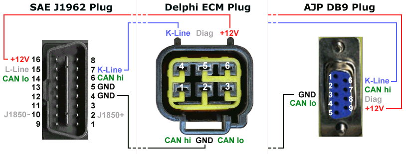



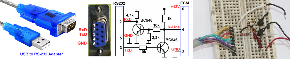
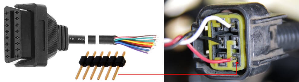
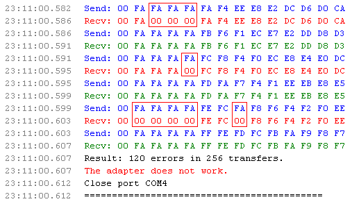

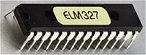

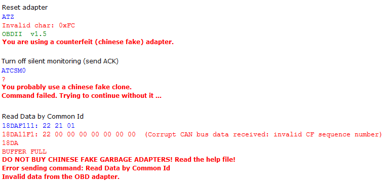


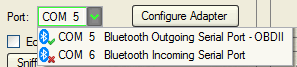
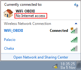
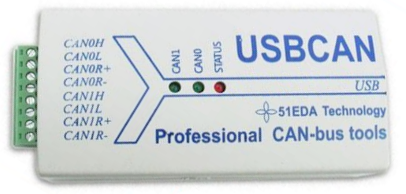
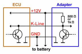
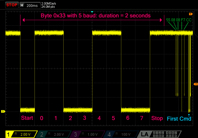
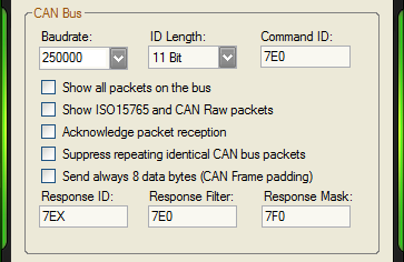
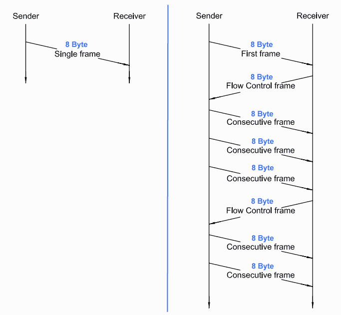





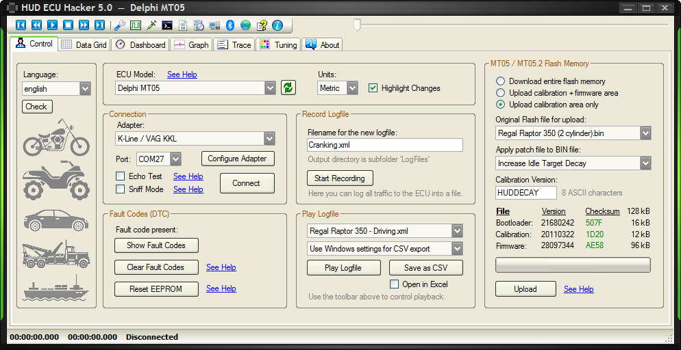
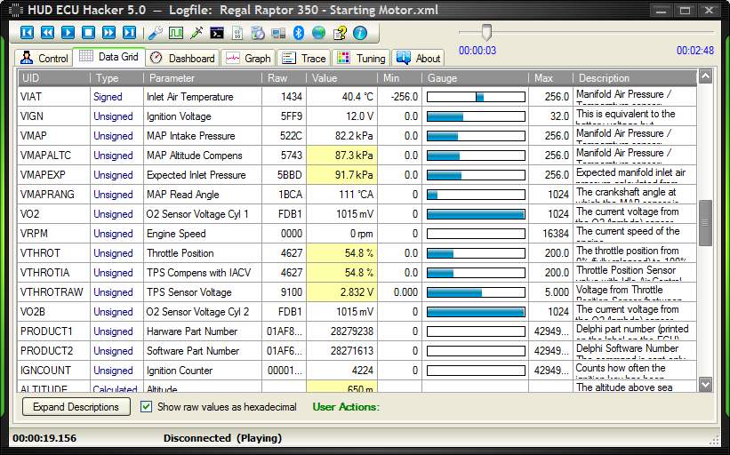
 You can click on it and modify these values in the ECU. See Data Slewing.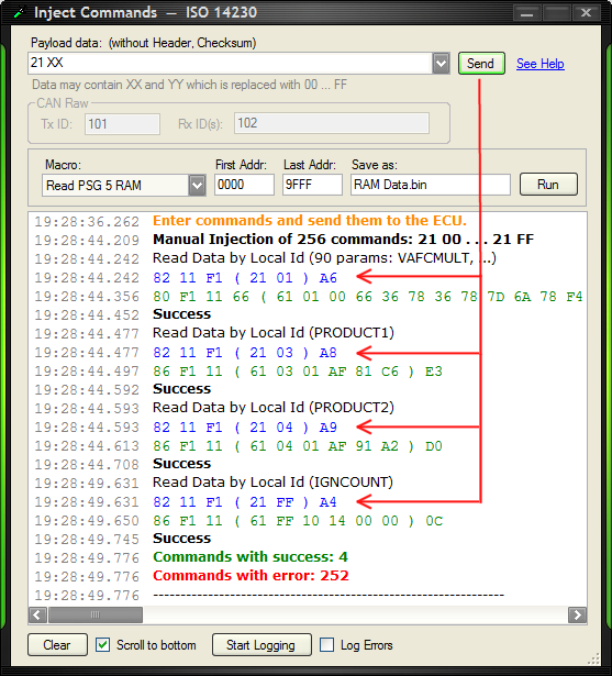
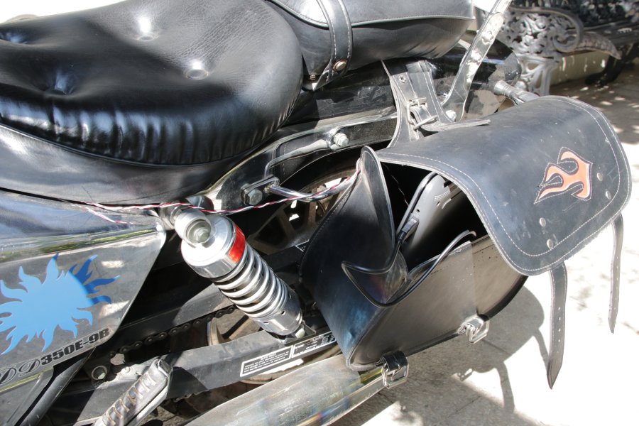
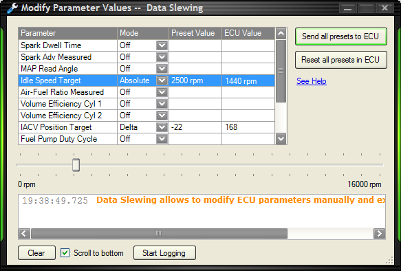
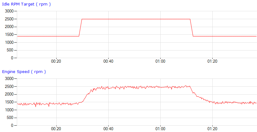
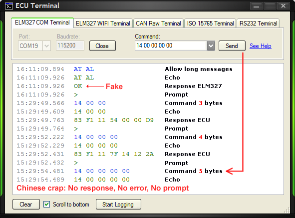
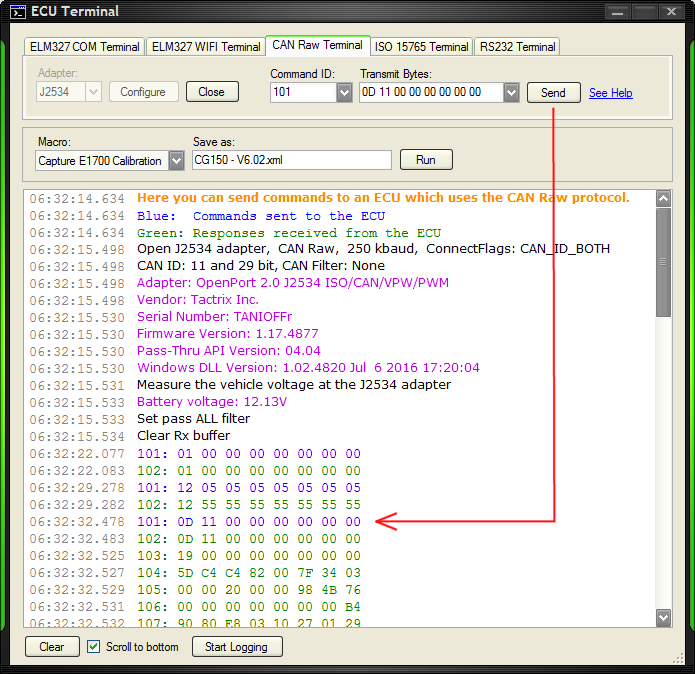
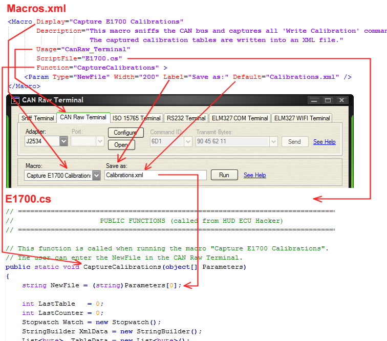

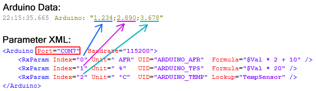
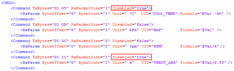
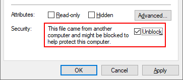

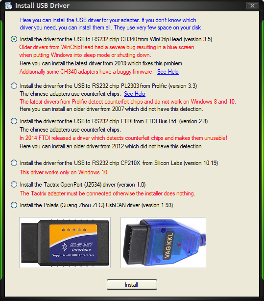

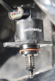
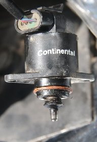
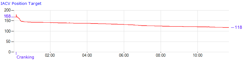

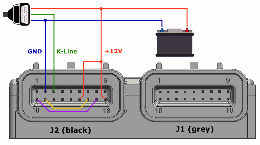
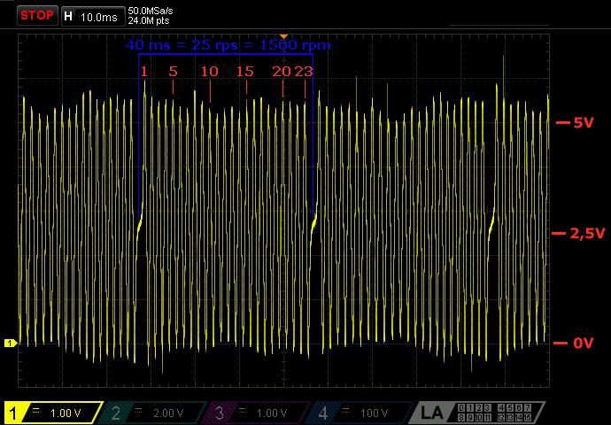
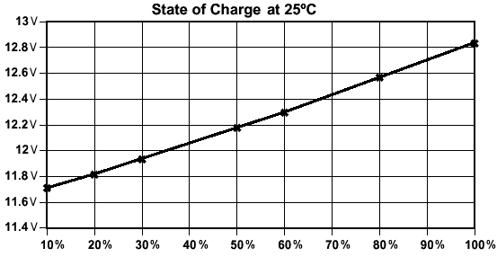
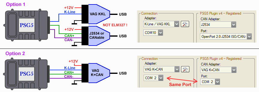
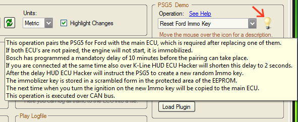
 You can write me in english, oder auf deutsch, o en español.