Oszi Waveform Analyzer is a masterpiece that converts your oscilloscope into a powerful analysis instrument
with features that you cannot find anywhere else.
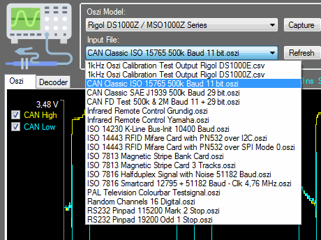
Oszi Waveform Analyzer comes with several pre-installed demo files that you should open one by one to discover all features.
These files are real-world oscilloscope captures that can show you how to use this program.
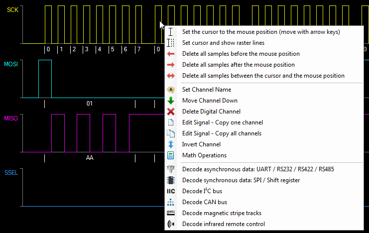
The menu is dynamic, which means that the menu items depend on what you click.
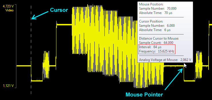
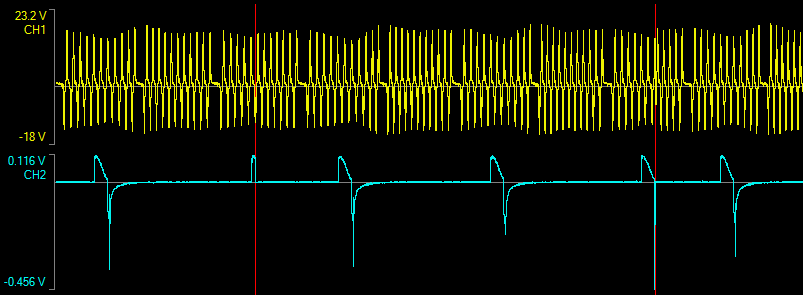
Oszi Waveform Analyzer allows a precise measurement of timing.
Above you see the interval of 64 µs and the calculated frequency of 15.625 kHz which is exactly the PAL television sweep frequency.
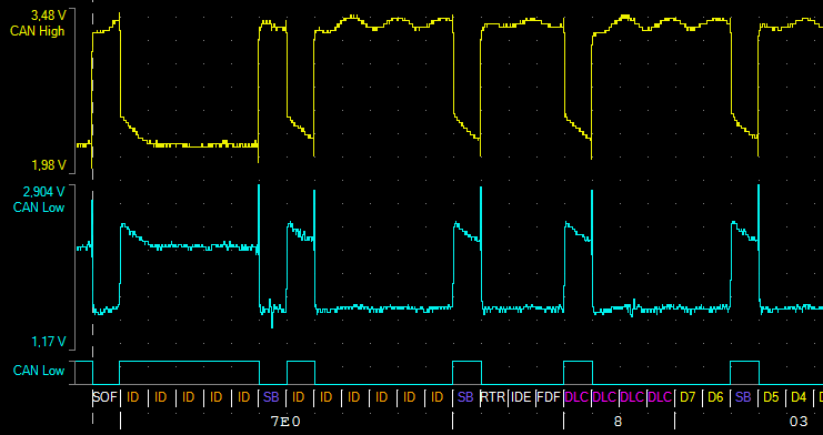
Here you see dotted vertical raster lines every 2 µs which corresponds to the CAN bus baudrate of 500 kBaud.
If you additionally press the SHIFT key the moving is faster.
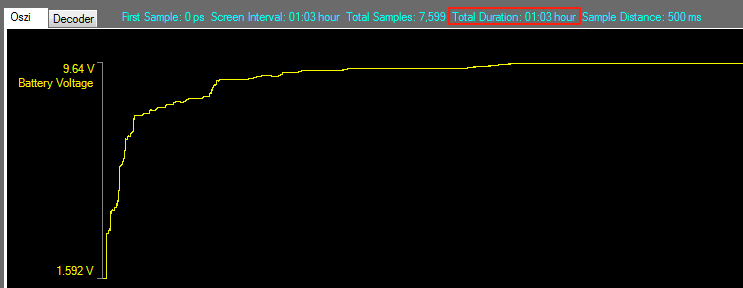
You can use the oscilloscope also to capture very slowly changing DC voltages.
This allows to capture processes that take hours or even days.
You can abort the capture whenever you like.
While a DC capture is in progress Oszi Waveform Analyzer prevents that the computer goes to sleep.
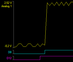
Here I have charged an empty 9 Volt battery over a 220 Ω resistor connected to a 12 Volt supply.
The plateaus are because of chemical processes and because the multiple cells inside the battery charge at different speeds.
Oszi Waveform Analyzer implements multiple algorithms for Analog / Digital conversion:
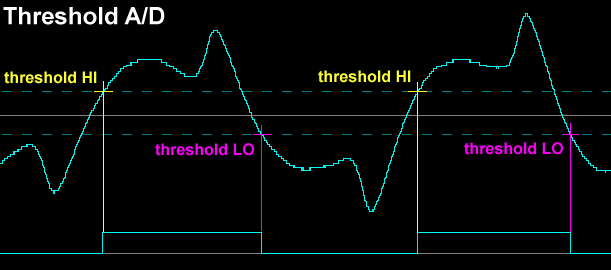
The standard method is the conversion at two threshold levels.
Digital High where the analog signal rises above the upper threshold and digital low where it falls below the lower threshold.
This is very simple and recommended for square analog signals, but not usefull for all signals.
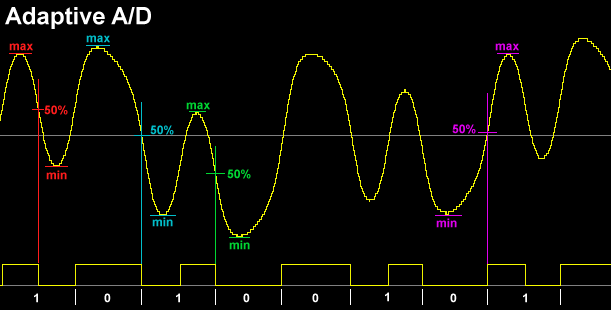
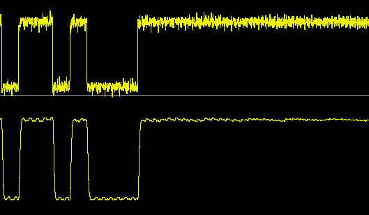
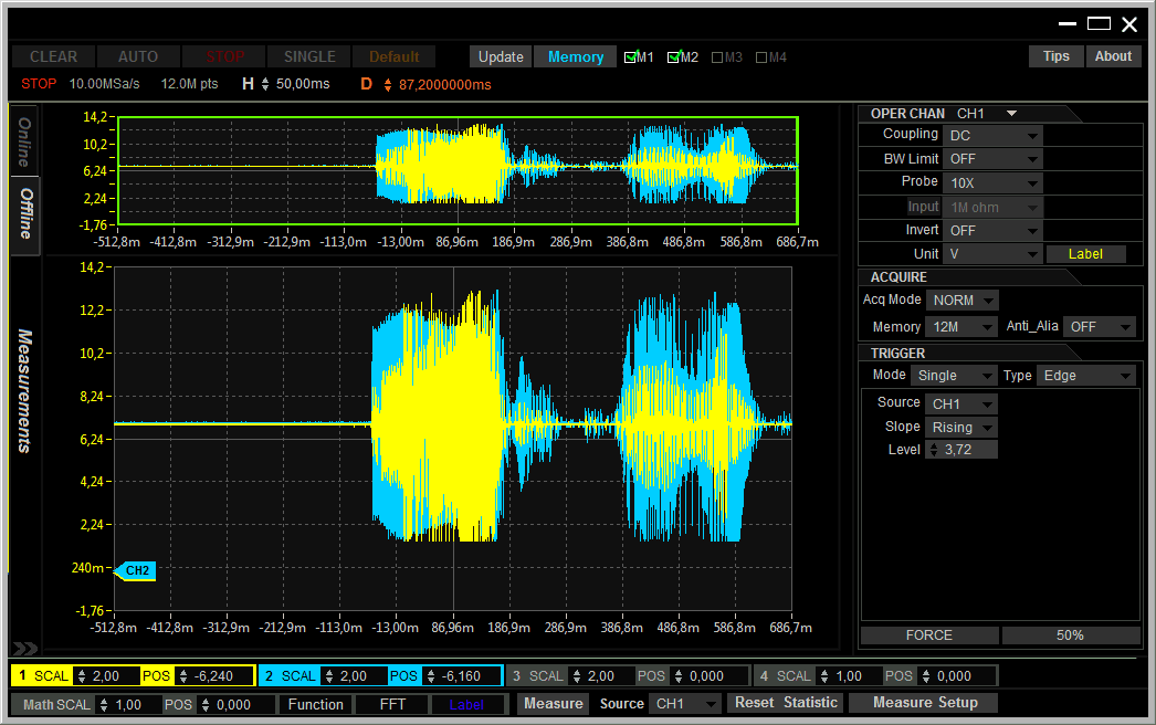
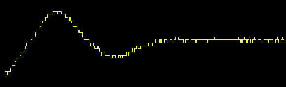
This is the signal of a magnetic stripe track which is extremely dancing up and down.
It is impossible to digitze this signal at a fix threshold voltage.
For the magnetic stripe decoder it is very important that the digital signal has 50% duty cycle.
This can be achieved by adaptive A/D conversion where the threshold adapts to the Min/Max values of each half period.
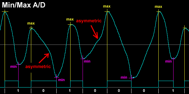
This is the most complicated signal because it is distorted and not symmetrical.
The threshold and adaptive methods will not work with this signal.
The only A/D method that results in a 50% duty cycle is Min/Max conversion where only the highest and lowest voltage are used.
This conversion also uses two thresholds to exclude noise on the analog signal.
To detect the maximum the voltage must be above the upper threshold and for the minimum below the lower threshold.
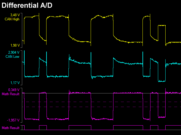
If you have differential signals like CAN bus, RS422 or RS485 it is recommended to first calculate the difference
before doing the A/D conversion. Use menu option Math Operations and create a new channel as CAN Low - CAN High
Then use Threshold A/D to create the digital channel.
The CAN Bus driver chips internally have a differential amplifier which does the same with the input signals.
Oszi Waveform Analyzer implements a noise filter (basically a low pass filter).
There are two settings that affect the signal in different ways.
The upper trackbar regulates the filter and the lower trackbar how often the filter is applied.
When you apply too much filtering the signal flanks are affected.
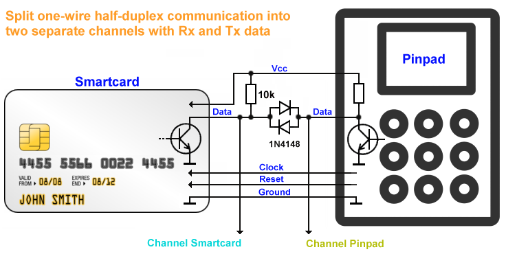
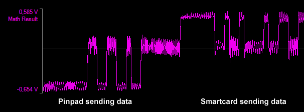
If you have a half duplex UART communication like for example a pinpad with a chipcard,
you see on the oscilloscope the Rx and the Tx data alternatingly but you will not be able to see
which bytes were sent by the pinpad and which bytes were sent by the smartcard.
How is it possible to separate a half duplex data transfer on one wire into Rx and Tx channels?
It is possible with 2 additional diodes and a resistor and Oszi Waveform Analyzer.
It contains the data transfer of an Ingenico pinpad reading a VISA credit card over diodes.
There is a lot of noise on the signal that comes from the 4.76 MHz clock which the pinpad sends to the card.
While one side pulls the data line to 0 Volt, the other side sees a voltage of 0.6 Volt.
The 0.6 Volt difference is the forward voltage of the 1N4148.
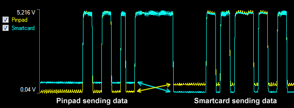
Now you get a 0.6 Volt negative signal for the pinpad and positive for the smartcard.
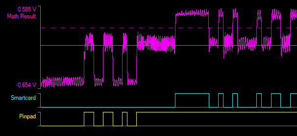
Then apply an A/D conversion once at +0.26 Volt and once at -0.28 Volt threshold.
Finally select menu option
Decode asynchronous data, then enable
Decode two halfduplex channels.
Set Baudrate: 51182 baud, Startbit: Low, Parity: Even, Stopbits: Two.
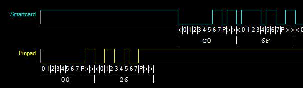
Mission accomplished: Now you see the bytes from the pinpad and the smartcard separated.
Decode Asynchronous Data
UART communication in all it's derivates like RS232, RS422, RS485, Smartcard,... either half duplex or full duplex
can be decoded after A/D conversion. The result is printed as coloured richtext output.
Additionally to decoding the bytes you can implement Post Decoders for specific UART traffic that show the meaning of the bytes.
I have designed Oszi Waveform Analyzer from the first day to be easily expandable.
You can write your own Post Decoder class for UART, I²C Bus and SPI Bus and register it in the PostDecoderManager.
Post Decoder ISO 7816
The next screenshot shows the UART demo file ISO 7816 Smartcard 12795 + 51182 Baud - Clk 4,76 MHz.oszi
It is a capture of a pinpad reading a VISA credit card.
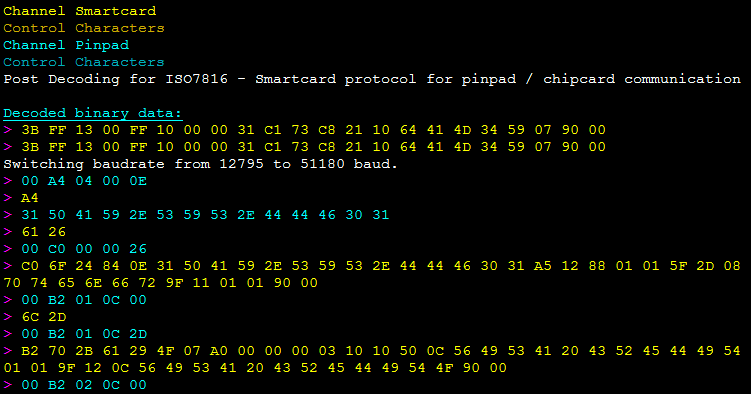
After the pinpad has pulled the Reset line the card sends autonomously the ATR (Answer to Reset) packet.
The pinpad sends a clock of 4.76 MHz and both start communication with a baudrate of 1/372 of the clock = 12795 baud.
Then pinpad and card switch to a baudrate of 4/372 of the clock = 51182 Baud which the card requests in it's ATR packet.
You must enable the post decoder ISO7618 which calculates and switches the baudrate otherwise you will see a lot of errors.
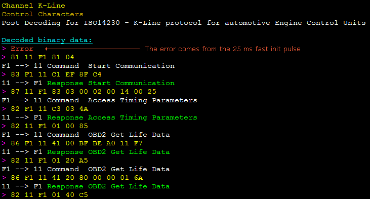
Post Decoder ISO 14230
The next screenshot shows the UART demo file ISO 14230 K-Line Bus-Init 10400 Baud.oszi.
It is captured from a motorbike ECU (Engine Control Unit). For more info read the help file of my software
HUD ECU Hacker which communicates over K-Line and CAN bus with ECU's from motorbikes, cars, trucks and vessels.
The white lines have been added by the Post Decoder.
Finally the UART demo files RS232 Pinpad 115200 Mark 2 Stop.oszi and RS232 Pinpad 19200 Odd 1 Stop.oszi
contain a capture of a command send from a POS (Point of Sale) to a pinpad over RS232.
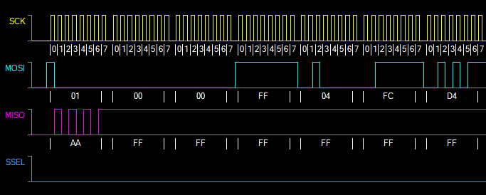
Decode Synchronous Data
Synchronous data refers to anything that has a Clock and a Data line.
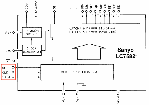
This may be a half-duplex or full-duplex SPI bus or a chip with a simple shift register.
For example the Sanyo LC75821 is an LCD display driver with a 56 bit shift register:
Oszi Waveform Analyzer supports packets up to 64 bit. If you have longer data you must decode them as bytes.
Open the SPI demo file ISO 14443 RFID Mifare Card with PN532 over SPI Mode 0.oszi
which shows the SPI bus communication between a Teensy processor and a Philips PN532 chip.
The PN532 is an RFID and NFC transmission chip that can read and write RFID cards at 13.56 MHz.
I use this chip in my project
RFID Secure Doorlock, a high-security door opener with RFID cards using DES or AES encryption.
In this project you find the detailed description and the programming manual of the PN532.
Post Decoder PN532 over SPI
You can implement Post Decoders for specific chips which process the SPI data and show the meaning of the bytes.
I implemented this for the Philips PN532:
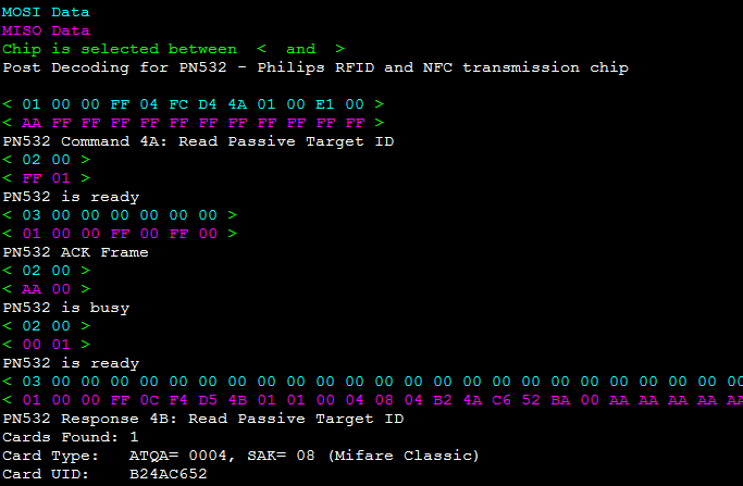
Here you see the PN532 reading an RFID Mifare Classic card.
The white lines have been added by the Post Decoder.
Decode I²C Bus
The same Philips PN532 chip from the last chapter can also be configured to operate over I²C Bus.
Open the I²C demo file ISO 14443 RFID Mifare Card with PN532 over I2C.oszi
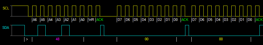
Post Decoder PN532 over I²C
You can implement Post Decoders for specific chips which process the I²C data and show the meaning of the bytes.
I implemented this for the Philips PN532:
Here you see the PN532 reading an RFID Mifare Desfire card.
The white lines have been added by the Post Decoder.
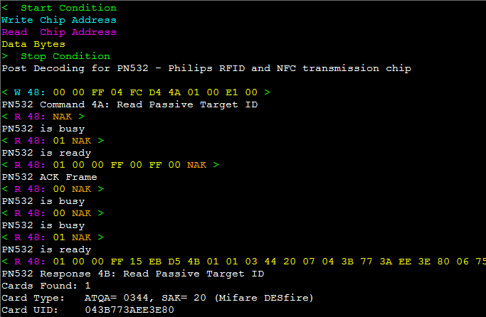
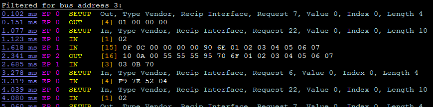
Decode USB Bus
The USB Full Speed decoder analyzes captures from the D+ and D- wires of a USB cable.
It decodes the USB tokens, detects several errors, verifies the CRC's, and decodes SETUP packets.
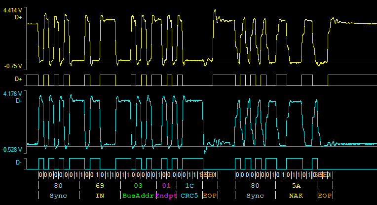
Here you see a host IN request for endpoint 1 of the USB device with bus address 3. The devices responds with NAK.
ATTENTION:
When you capture on a USB cable you do not only see the USB traffic with the connected USB device.
All traffic from the host computer comes from the USB Root Hub on the mainboard or an external USB hub.
The USB hubs do not filter host requests. If you connect the oscilloscope to the USB cable of the device 3
you will also see host requests to USB devices with addresses 2, 4, 7,... that are connected to the same hub.
But you will not see the responses of any other device than device 3. This may be confusing in the beginning.
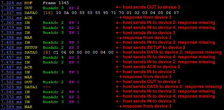
Oszi Waveform Analyzer detectes automatically to which device you have connected and decodes only traffic with this device.
Read Part 3 in the excellent
USB Tutorial.chm in subfolder
Documentation.
Decode CAN Bus
The CAN bus decoder is the most complex of all decoders (1100 lines of code).
It can also decode CAN FD (Flexible Datarate) with two different baudrates and up to 64 data bytes per packet.
It has a fully implemented error detection (timing errors, bit stuffing errorrs, parity errors, CRC errors,...)
It is a great help if you have to analyze errors in a CAN network.
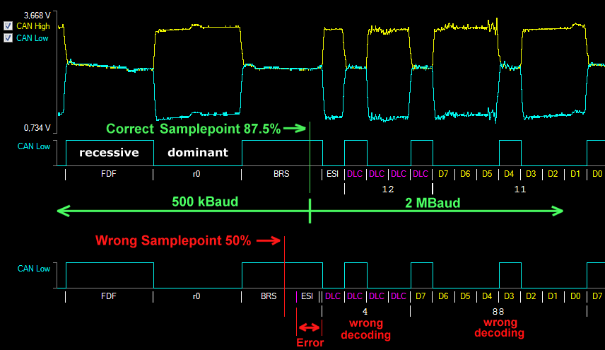
When decoding CAN Classic you don't have to care about the samplepoint.
But the CAN FD protocol switches the baudrate at the samplepoint of the BRS (Baud Rate Switch) bit.
This makes the samplepoint crucial for a correct decoding.
You cannot decode CAN FD packets if you don't know the samplepoint of the CAN network.
The CAN network may even use a different samplepoint for each baudrate.
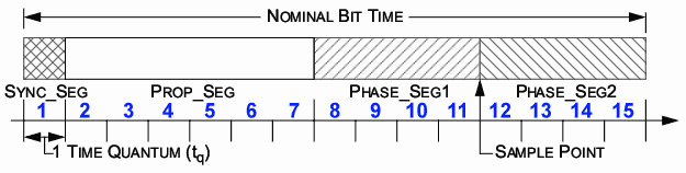
This image is from the file
Bosch CAN FD.pdf that you find in subfolder
Documentation.
In this example one bit of a CAN packet is divided into 15 time quantums.
The samplepoint is after the eleventh quantum which results in a samplepoint at 11/15 = 73.33%
The BRS bit uses the standard baudrate until the samplepoint and the rest of the bit uses the CAN FD baudrate.
Example:
Standard baudrate = 500 kBaud = 2 µs / bit
CAN FD baudrate = 2 MBaud = 500 ns / bit
Both samplepoints = 50.0% → BRS bit = 50.0% of 2 µs + 50.0% of 500 ns = 1000 + 250 = 1250 ns
Both samplepoints = 87.5% → BRS bit = 87.5% of 2 µs + 12.5% of 500 ns = 1750 + 62.5 = 1812.5 ns
As you see the difference is 562.5 ns which is more than the length of one entire bit.
If you enter an invalid samplepoint, all bits after the BRS bit will be decoded wrongly.
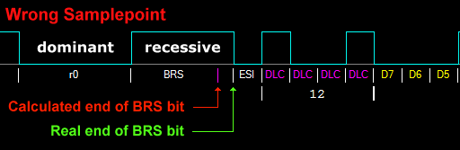
If you don't know the samplepoint of your CAN network, Oszi Waveform Analzyer helps you to find it.
When you enter the wrong samplepoint you will see a lot of decoding errors.
Adjust the samplepoint until the real end and the calculated end of the BRS bit match.
The calculated end of the BRS and the DL1 bits, where baudrate is switched, are displayed with a magenta line.
If the samplepoint is correct the magenta line will be covered by the white line of the start of the next bit.
The ESI (Error State Indicator) bit after the BRS bit is normally low, except the CAN controller reports errors.
CAN nodes and Oszi Waveform Analyzer re-synchronize on received edges from recessive to dominant.
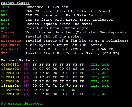
This is the decoder result of the J1939 CAN bus traffic of a
Kenworth truck.
If you work with CAN bus I highly recommend that you download my software
HUD ECU Hackerwhich also decodes ISO15765 and J1939 and has a CAN bus debugger where you can send packets manually.
It supports multiple cheap CAN bus adapters ($20 USD).
You can even write macro scripts to transmit / receive and decode CAN bus traffic.
Decode Magnetic Stripe Tracks
You think the magnetic stripe on cards is from the past and obsolete?
It may be in your country, but I can assure you that still in the year 2025 it is used in other parts of the world.
Who needs this if there are magnetic stripe readers ready to buy?
I work on an automation robot for QA of POS (Point of Sale) and have to simulate a user sliding a card through a card reader.
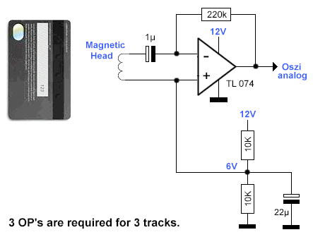
A special hardware of my robot injects a magnetic field for each track with 3 tiny coils inside the card slot.
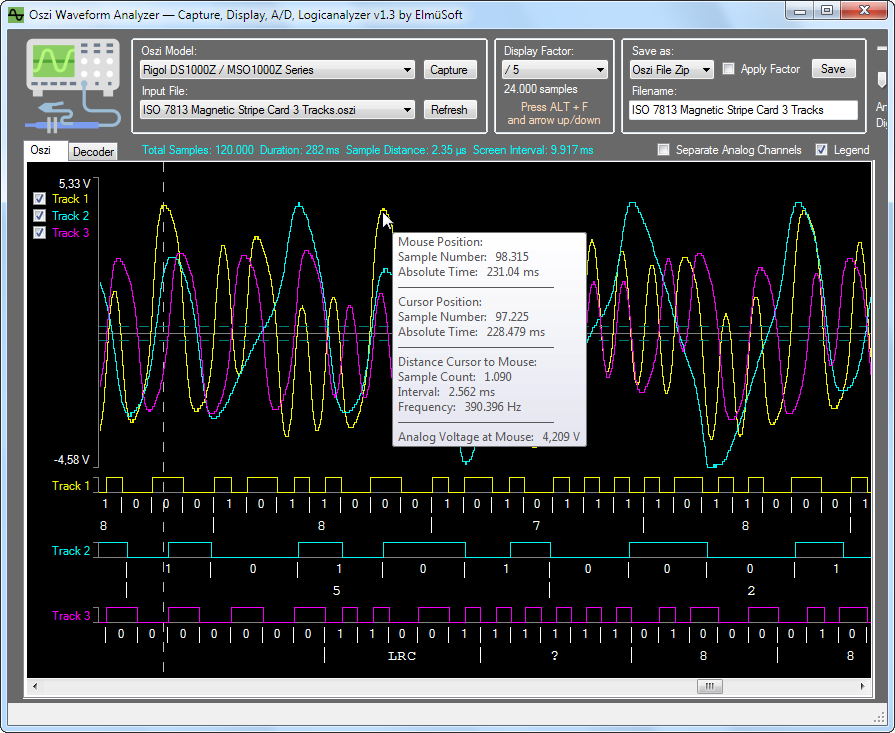
The demo file ISO 7813 Magnetic Stripe Bank Card.oszi has been captured from sliding a VISA debit card with this amplifier:
The MagStripe decoder was a challenge, not because of the decoding, but because the A/D conversion of the analog signals is difficult.
The analog sine wave must be converted into a square wave of 50% duty cycle, otherwise the decoder will not work.
The track data is encoded using 2 frequencies, one beeing the double of the other.
One half period of the slow frequency encodes a binay 'zero' and an entire period of the high frequency encodes a binay 'one'.
The
A/D conversion must be very precise because a half period already encodes one bit.
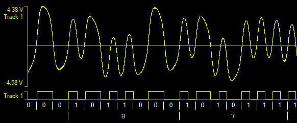
The analog signal is dancing up and down. A fix threshold does not work here.
Here you see a perfect conversion of Track 1 using Adaptive A/D:
Track 2 is the most difficult track. Oszi Waveform Analzyer tries Min/Max A/D conversion if Adaptive A/D does not work.
The frequency of Track 1 is 14/5 times higher than the frequency of Track 2.
Additionally the baudrate is varying, it depends on the manual sliding speed. The decoder must permanently re-synchronize to the signal.
Additionally the entire data may come reverse, depending on the sliding direction of the card.
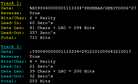
This is the result of the Magnetic Stripe decoder. Track 3 is empty on bank cards.
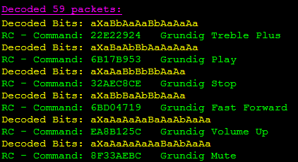
Decode Infrared Remote Control
which can control the MP3 player on the computer with the IR remote control of a TV, amplifier, DVD player, SAT tuner or whatever.
It connects over USB to the computer and injects keystrokes which control any music player that can be controlled by the keyboard.
It uses a universal decoder which first detects the length of one bit and then measures how many bits are High or Low.
The bit lengths are converted into characters ("A" for 1 bit, "B" for 2 bit,...) and then a CRC is calculated for each button.
This works with ANY remote control, no matter what baudrate or data format.

Waveform Transfer to the Computer
Rigol UltraScope
Once upon a time I used UltraScope to transfer captures to the computer.
 |
| Show Full Size |
Rigol UltraScope requires that you first install the huge UltraSigma (530 Megabyte installer).
UltraScope is nothing more than a remote control of the oscillosope.
It has absolutely no analysis or decoder functionality.
You can only save waveforms as CSV files. A 24 Megasample capture occupies 300 Megabyte on the disk.
This huge software is completely useless.
SCPI Protocol
Most oscilloscopes implement the SCPI protocol (Standard Command for Programmable Instruments).
It is a very primitive text based protocol that can remote control an instrument and transfer waveforms to a computer.
If an invalid command is sent to the device, the protocol defines that the device should not respond.
This results in a timeout without knowing what went wrong. (SCPI was designed by very smart people!)
The text based commands are not standardized at all. Each manufacturer uses his own commands and parameters.
It is impossible to write universal code that communicates with all oscilloscopes.
Additionally many SCPI devices have ugly bugs that require specific workarounds.
I have implemented the SCPI commands for the Rigol series DS1000Z and DS1000DE.
Rigol is such an inconsistent company that not even for their own products they have any standard.
Each serie requires different commands with completely different parameters and responses.
Prerequisites
To use the SCPI protocol the oscilloscope companies tell you to install a huge runtime that communicates with their device.
These will fill your harddisk with hundreds of Megabytes and you will have 12 (twelve!) services
that run permanently in the background!. Really? All this just to transfer simple text commands?
That is ridiculous! This is like throwing an atomic bomb to kill a bug.
You need NO RUNTIME when you use Oszi Waveform Analyzer, because it connects directly to your scope.
The only required installation is the tiny TMC (Test and Measurement Class) USB driver of 24 kilobyte.
After installing this driver from the IVI Foundation you see your oscilloscope in the Device Manager:
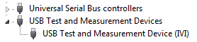
You can install the USB driver with the button Install Driver:
Transfer Window
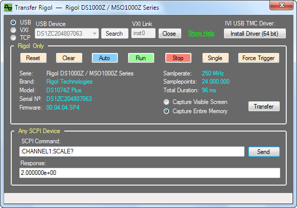
This window has two parts:
The upper part sends Rigol-specific commands that will only work if you have selected the correct Rigol serie.
With the buttons Run, Stop, Single, etc you can remote control the oscilloscope from the computer.
Also the display of samplerate, samplepoints, etc requires Rigol-specific commands.
With the button Transfer you can transfer the stored signals of all enabled channels to the computer.
You can chose to copy only the visible screen of 1200 samples or the entire memory of 24 Mega samples.
The Rigol serie DS1000DE has only memory for 1 Mega samples, so you will see other values here.
The
middle part allows to capture very slow processes. See
DC Capture.
The lower part works with any SCPI device (oscilloscopes, function generators, multimeters, spectrum analyzers,...)
The button Send sends any SCPI command to any SCPI device and shows the response.
For example :CHANNEL1:SCALE? asks the vertical scale of analog channel 1. The response is: 2 Volt/raster unit.
Current Implementation of SCPI Commands
| Oscilloscope Brand | Serie | File Import | SCPI Transfer |
|---|
| Rigol | DS1000Z | CSV | USB, VXI, TCP |
| Rigol | MSO1000Z | CSV | USB, VXI, TCP |
| Rigol | DS1000D | CSV | USB (no RJ-45 plug available) |
| Rigol | DS1000E | CSV | USB (no RJ-45 plug available) |
| OWON | VDS1022 | CSV, BIN, CAP | not yet implemented |
| OWON | VDS2052 | CSV, BIN, CAP | not yet implemented |
| Picoscope | 3206 MSO | CSV | not yet implemented |
| Tektronix | TODO | Download Manual |
| Rohde & Schwarz | TODO | Download Manual |
| Agilent | TODO | Download Manual |
| Siglent | TODO | Download Manual |
| Keysight | TODO | Download Manual |
| Hantek | TODO | Download Manual |
| Other Brands | TODO | Use Google ... |
Now it is up to you to implement further oscilloscope models.
Download the programming manual that explains the SCPI commands.
Open the above Transfer window and send the SCPI commands manually to see what your scope responds.
I have designed Oszi Waveform Analyzer from the first day to be easily expandable.
Clone the Rigol classes, rename and modify them and register the new oscilloscope serie in the TransferManager.
The SCPI Library for C# Programmers
As this project is open source you can use the class SCPI also in your own C# project.
It allows you to communicate with any SCPI device over USB, VXI or TCP.
My code will keep your harddisk clean. You do not need to install the NI-VISA monster of 1 Gigabyte.
In the class SCPI you can enable TRACE_OUTPUT to see the SCPI commands and responses.
In the subfolder
Documentation you find a
logfile of the SCPI commands and responses of my scope.
Connection over USB, VXI, TCP
Oszi Waveform Analyzer offers 3 options to connect to your oscilloscope:
Option 1: USB Connection
USB is the easiest connection with the fastest transfer.
All you have to do is connect the USB cable and install the IVI driver.
But if you have an oscilloscope that implements a proprietary USB interface the IVI standard may not be supported.
Then Oszi Waveform Analyzer will tell you that no USB device of type 'Test and Measurement Class' was found.
The following 2 chapters explain how to connect over ethernet.
ATTENTION: If you have an oscilloscope from a sloppy brand like Rigol you may have an ugly bug:
My Rigol will not connect over ethernet anymore if the USB cable was once connected. (see
bug report)
Option 2: VXI-11 Connection
If your oscilloscope has an ethernet RJ-45 plug, it probably supports the VXI-11 protocol.
VXI (VME eXtensions for Instrumentation) is a standard for network communication between instruments and controllers.
The implementation of the VXI protocol was quite complex: 1100 lines of source code.
VXI-11 is a well designed protocol that has a port mapper on TCP and UDP port 111.
When you click the button Search, Oszi Waveform Analyzer sends a broadcast request to port 111.
If a VXI-11 capable device is connected, it will send a response that contains the core VXI port of the device.
So with one click you get instantly the IP address and the listening TCP port of your oscilloscope.
My Rigol listens on port 618 for SCPI commands wrapped into VXI-11 packets.
ATTENTION: If you have an oscilloscope from Rigol that uses the unintelligent default IP address
169.254.109.240 and your network is 192.168.XXX.YYY, the broadcast request will be blocked by the network mask.
I recommend to configure a
static IP address. Also DHCP mode does
not work correctly in a Rigol oscilloscope.
The VXI-11 protocol allows an 'Instrument' (oscilloscope) to contain multiple logical 'Devices':
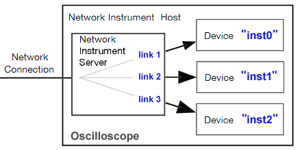
Each device has a logical name that you must know, otherwise you cannot connect.
Rigol, Agilent, Keysight and other brands use the device name inst0 which is case sensitive.
But it may also be inst1 or inst2 or gpib0 or gpib1 or gpib0,4 or gpib0,6, ....
If you have tried to connect with inst0 and get an error, search the VISA Address of your oscilloscope.
After pressing the buttons Utility, IO Settings and Lan Config my Rigol shows this information:
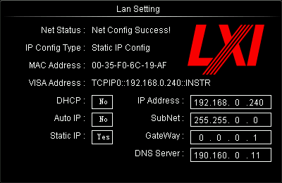
Here the VISA address does not contain the logical device name, which indicates that the default name inst0 has to be used.
But in other instruments you may get:
TCPIP::A-52230A-04585.local::inst1::INSTR where the device name is inst1.
TCPIP0::DK78192::gpib0,2::INSTR where the device name is gpib0,2.
If nothing of this works you must run a software from the manufacturer that can communicate with your scope.
Then use
Wireshark to sniff the network traffic and search for the VXI-11 command
CREATE_LINK Call:
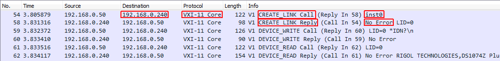
Here you see that a link is created to the logical device with the name inst0.
Make sure that the CREATE_LINK Reply does not return an error. Some software tests multiple names until one works.
Enter the case sensitive name in Oszi Waveform Analzyer under VXI Link and you are ready to connect.
Option 3: TCP Connection
Some oscilloscopes additionally accept SCPI commands over a plain TCP connection.
In this case no complex protocol like VXI-11 is used. The SCPI text commands are simply put into TCP packets.
My Rigol listens on TCP port 5555 for SCPI commands. But this port is completely undocumented.
Your scope may use another port or not support this communication at all.
You can use a port scanner to find all listening ports.
Transfer Speed
USB:
If your scope implements Full speed USB, the maximum transfer rate is 12 MBit/sec.
If your scope implements High speed USB, the maximum transfer rate is 480 MBit/sec.
Ethernet:
If your scope implements Fast Ethernet, the maximum transfer rate is 100 MBit/sec.
If your scope, router and computer support Gigabit Ethernet, the maximum transfer rate is 1 GBit/sec.
If your computer connects over WIFI you will have a significantly worse performance.
My Rigol has 480 MBit USB and 100 MBit ethernet and a waveform transfer is 4 times faster over USB.
And plain TCP transfer is approx 30% faster than VXI transfer.
But the speed depends on many factors.
Oscilloscope manufacturers use cheap processors too keep the price low.
The processor has to control the entire oscilloscope and often does not have much power left for data transfer.
When you enable TRACE_OUTPUT in the SCPI class you see how slow the processor responds to some commands.
A primitive command like :WAVEFORM:STOP, which only stores a value in the scope, may takes 80 ms to execute!
And over the VXI protocol my Rigol sends 24 Megabyte sample data in ridiculous chunks of 396 bytes!
This shows how intelligent Rigol engineers are. The theoretically possible network speed is wasted.
You find a logfile of VXI transfer in the subfolder
Documentation.
Storing Waveforms on Disk
CSV Files
Most oscilloscopes offer the option to store the capture in a CSV file.
The rows of the CSV file contain the analog voltages as floating point values, each channel in it's own column.
The problem is how to transfer the X axis settings, like timestamp and samplerate in a CSV file?
Here each manufacturer cooks his own soup.
And Rigol, the most inconsistent company under the sun, does not even use the same CSV format in their own products.
I implemented a CSV parser into Oszi Waveform Analyer. And I had to write a different code for each Rigol serie.
The Rigol DS1000DE serie stores the timestamp in the first column (with rounding errors):
Time,X(CH2),
Second,Volt,
-2.4000157e-04,-0.00000e+00,
-2.3600156e-04,-4.00000e-02,
-2.3200156e-04,-0.00000e+00,
-2.2800156e-04,-4.00000e-02,
-2.2400156e-04,-4.00000e-02,
-2.2000156e-04,4.00000e-02,
etc.... |
This is not an intelligent format because in each sample they need 15 ASCII characters for the timestamp.
With 1 Megasamples they store 15 Megabyte only for the useless timestamps.
In the first 2 rows they send the channel names and other stuff which is undocumented.
The long floating point voltages are a waste of disk space because the A/D converter in the scope has only 8 bit resolution.
Rigol developers are not smart enough to remove the useless trailing zeroes.
Instead of "-0.00000e+00" they could easily send "0" and reduce the file size significantly.
And the Rigol DS1000Z serie stores a completely useless counter in the first column:
X,CH1,Start,Increment,
Sequence,Volt,-1.144000e-03,2.000000e-06
0,4.00e-02,
1,-1.20e-01,
2,-1.20e-01,
3,4.00e-02,
4,4.00e-02,
5,-1.20e-01,
etc.... |
The format of the first two rows is completely different than in the DS1000DE and - obviously - undocumented.
I found that the last value in the second row is the time distance between two samples in seconds.
Both formats are among multiple examples for the lack of intelligence of Chinese Rigol developers.
I'am sure that other oscilloscopes use completely different CSV formats, so each serie requires it's own CSV parser.
A full 24 Megsample capture of my scope occupies 300 Megabyte in a CSV file.
If I store only 3 captures on disk they already occupy 1 Gigabyte!
The CSV format is totally obsolete.
WFM Files
Rigol also offers to store a capture in a WFM (WaveForM) file.
This occupies less disk space because it is a binary format.
The problem is that this format is undocumented, and guess what?
Each Rigol serie uses a completely different file header and content.
I found a WFM file format description from Tektronix, but they say it was developed for internal use.
Apart from the waveform data they store all the hundreds of oscilloscope settings, that you will never need.
They store for example the trigger voltage, trigger mode, AC/DC coupling, probe ratio, etc...
All this useless information makes a WFM file parser extremely complex.
I will not implement a dozen of complicated parsers for undocumented WFM file formats into Oszi Waveform Analyzer.
And tomorrow Rigol will sell a new serie which uses just another different WFM format.
The WFM format is obsolete.
OSZI Files
So, how to save signals using few disk space and using a simple file format?
As this file format does not exist, I created it.
When you start Oszi Waveform Analyzer it registers the file extension *.oszi
What does OSZI stand for? "Oscilloscope" is in German "Oszilloskop" and the abbreviation is "Oszi".
The OSZI file format is open-source and free of any license.
An OSZI file uses the maximum compression that is possible, but it is still a lossless format:
How much disk space an Analog Channel requires depends on the analog resolution of the A/D converter in the oscilloscope.
My Rigol has an analog resolution of 8 bit, so each sample can be stored lossless in one byte.
But an OSZI file can also store any other A/D resolution, like for example 10 bit.
In this case exactly 10 bits are stuffed together until a byte is full and written to disk.
If 10 bits would be stored as two bytes, 6 bits would be wasted.
More resolution than 12 bit does not make sense because your monitor cannot even display the 4096 vertical pixels of 12 bits.
And if you want to save disk space you can even reduce the bit resolution in the OSZI file as you like.
A 12 bit resolution can be reduced to 8 bit and the file is 50% smaller.
For Digital Channels Oszi Waveform Analyzer choses automatically the best compression algortithm:
The Mask compression stores one bit per sample and channel and stuffs the bits together until a byte is full.
For example for 3 digital channels A,B,C the first byte stuffs the bits like: ABCABCAB, the next byte CABCABCA, ...
But mostly RLE compression (Run Length Encoding) is more efficient because digital data has long periods of the same status.
It only stores the count of samples util the next change of the digital status.
For example 119 consecutive samples that are all High or Low are compressed into in only one byte.
For example 15894 consecutive samples that are all High or Low are comrpessed into only two bytes.
Although this is already a very good compression, you can additionaly apply a ZIP Compression.
This decreases the file size even more.
Look at the demo OSZI files which are installed with the program and study their file size.
The file ISO 7816 Smartcard 12795 + 51182 Baud - Clk 4,76 MHz.oszi has 3 channels with 2 million samples and occupies 5 kB.
The OSZI file can store up to 255 cannels. Each channel can have analog data or digital data or both.
Also the names are stored that you have assigned to the channels.
The entire OSZI file is secured by a CRC check, so corrupt files will always be rejected.
I implemented a version number into the file so future extensions are possible.
After running the program for the first time it registers the file extension OSZI.
You can then double click any OSZI file anywhere on your disk and it will open in Oszi Waveform Analyzer.
The folder in which you have double clicked the file will be your new working folder for further open/save operations.
Other File Formats
If you want to import or export other file formats you can write an extension.
I have designed Oszi Waveform Analyzer from the first day to be easily expandable.
Write a new file parser class and register it the ExImportManager.
The new file export will be added to the list of "Save as" options:
Save File Options
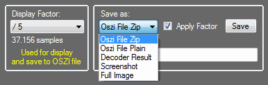
A Display Factor of 1 means that one sample corresponds to one pixel on the screen.
Oszi File Zip: Save the capture as OSZI file with additional ZIP compression.
Oszi File Plain: Save the capture as OSZI file without ZIP compression.
Decoder Result: Save the text output of the decoder and post decoder into a RTF file.
Screenshot: Save a screenshot of the currently visible signals as PNG file.
Full Image: Save a PNG image of the entire signal, also the part that is not visible on the screen.
If the checkbox Apply Factor is NOT checked the capture is stored in full resolution (e.g. 24 Mega samples) into the OSZI file.
If Apply Factor is checked the factor is applied to the display and also to the OSZI file.
If you select for example a display factor of "/ 5" the OSZI file stores every fifth sample reducing resolution and file size.
Below the combobox "Display Factor" you see the samples (37156) that the OSZI file will contain.
ATTENTION: If you reduce the resolution too much, some decoders will not work anymore.
For example the UART and CAN bus decoders need at least 12 samples per bit for a reliable detection.
Display of Multiple Frames
This is a capture from a running motorbike. Above the crankshaft sensor, below the spark coil.
You find this in the sample file "Yamaha XTZ 250 CKP + Spark Coil OWON VDS 1022.cap".
Files with extension CAP are a proprietary and undocumented OWON format, that Oszi Waveform Analyzer can import.
As you see the signal is crippled. Large parts are simply missing.
This capture has been recorded by a very cheap Chinese oscilloscope: the OWON VDS 1022.
This oscilloscope has a ridiculous capture buffer of 5 kilobyte.
For any professional use this is insufficient. Also the software from OWON is of poor quality.
OWON offers the possiblity to capture frames continuously. It fills the tiny hardware buffer and sends it over USB.
But this is not a real time capture and they use only Full speed USB (12 MHz) which is too slow.
So you see only snippets (frames) from the original signal, the parts between the snippets are lost.
Oszi Waveform Analyzer draws a red line each time one capture frame ends and the next frame starts.
Download & New Versions
If you have experience in C# programming you can add new features to the next version.
Transfer from new oscilloscope models can be added to the class TransferManager.
New operations in the right-click menu (e.g. decoders) can be added to the class OperationManager.
New file formats for export and import can be added to the class ExImportManager.
New post decoders for UART, SPI, I²C data can be added to the class PostDecoderManager.
For Linux and Mac a small class for USB transfer must be added to the PlatformManager. See comments in source code.
If you have problems with the communication over USB you can enable debugging with TRACE_OUTPUT in the class SCPI.
When you add new features I recommend to clone an existing class and make all the required adaptions.
Please study the
source code thoroughly until you understand it before you write any new code.
If you write a new decoder it is mandatory that you provide a good quality OSZI file for testing it.
Please send me an email if you want to support this project. May be someone is already working on your task.
| Program | Version | Date | Size |
|---|
|
Oszi Waveform Analyzer | 2.6 | 3.apr.2026 | 3.2 MB |
Should I buy a Rigol Oscilloscope?
Rigol is a Chinese company that has absolutely no Quality Control.
They sell their products as they are: Full of ugly bugs.
I did not find only 1 or 2 or 3 bugs in my scope. The bugs are uncountable.
I still find new bugs as soon as I use a feature that I did not use before.
As many other Chinese companies, Rigol sells products that are cheaper, but of the worst quality.
I'am working with electronics since 40 years, but I have never seen such a plentitude of bugs.
If you write to the Rigol support they will tell you that the bug is confirmed and they are working on it.
But they will not fix their bugs. They don't care about you. You are naive if you expect anything from the Rigol support.
If they would care about their customers they would fix their bugs before bringing a new serie on the market.
Why should Rigol fix the bugs in your oscilloscope? This is not profitable. You already have paid.
Bug in DS1074Z
Once I tried to store the current signal on the screen into a CSV file.
I put my USB stick into the front plug of the oscilloscope and selected: Save as CSV.
After that my USB stick was not readable anymore. The oscilloscope killed my USB stick!
I had to format the USB stick to make it usable again.
All the several files and folders that I had before were gone forever.
Bug in DS1074Z
It also happened that I plugged in a USB stick and the oscilloscope was completely frozen. All buttons were dead.
Bug in DS1074Z
My oscilloscope can save the current screen into a CSV file.
But when I chose to store the entire memory of 24 Megapixels to CSV, I get this:
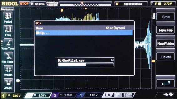
The progressbar runs to the middle and stays there forever.
The file is never written. You can wait 3 hours with no advance.
The same happens when I save a WFM file. This is 100% reproducible.
But the oscilloscope is not crashed. After pulling out the USB stick it shows an error and works again.
A sloppy Chinese developer has programmed an endless loop.
Bug in DS1074Z
A very severe bug is that you switch the scope into SINGLE trigger mode where it waits for a signal.
Then comes the signal and the scope triggers, but on the screen there is only a zero line!
Even if you reduce the horizontal resolution to see the entire capture memory: There is absolutely no signal.
Not even the most basic things are functioning. What an incredible garbage!
Bug in DS1074Z
When I move the knob that shifts the signal horizontally on the screen too fast I may get this:
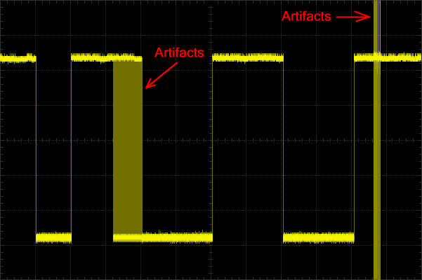
The square signal suddenly has ugly artifacts.
These artifacts are not temporary. They stay. If I contiue to move the knob too quickly I even get more of them.
What a Chinese garbage!
Bug in DS1074Z
When I select the horizontal resolution of 500 ms per raster unit I get a wrong timing of all signals.
I capture the same signal with 200 ms per raster unit or any other setting and the timing is correct.
I posted this bug on
StackExchange.
Others have confirmed to observe the same even on other oscilloscope models.
On this page you also find the experience of others with the Rigol support.
Bug in DS1074Z
The RS232 decoder does not work at all if you switch the screen resolution to see more than 2 or 3 bytes at once.
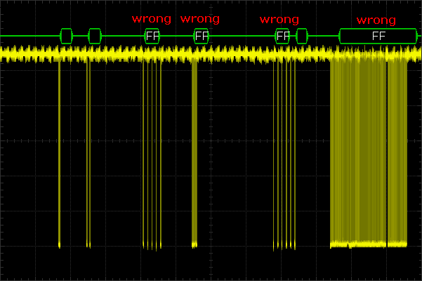
There is not even one single byte "FF" in the real data.
How is it possible that the RS232 decoder depends on the screen resolution?
I would understand that the decoder turns off when the space on screen is too small. But it displays wrong values.
And Rigol wants you to pay extra money for a
license to "unlock" their primitive decoders!
What a luck that you don't need this crap anymore, now that you have Oszi Waveform Analyzer.
Bug in DS1074Z
After configuring the LAN settings, enabling DHCP mode and clicking Apply the scope gets an IP address from DHCP.
After turning the scope off and on, it will be back in mode "Auto IP" with a useless IP of 169.254.109.240
The scope is so sloppy that DHCP mode works only once and only manually.
Bug in DS1074Z
If the USB cable was once plugged in, a connection over TCP is impossible.
After disconnecting the USB cable the scope will still not respond over TCP.
To use TCP or VXI the scope must be turned off and on again without USB cable. What an INCREDIBLE GARBAGE!
Bug in RPL1116
I bought my scope with an extension for 16 digital inputs: The RPL1116 Active Logic Probe.
I connected one analog input and two digital inputs to the same 1 kHz test output and got this:
How is it possible that the digital channels have a tremendous phase shift?
This is not a high frequency. It is only 1 kHz. This Chinese toy is useless for any serious work.
Bug in DS1102E
If the SCPI protocol would be intelligently designed it would demand a respone to every command.
- If the command returns a value, the value is sent.
- If the command has no return value, a simple "OK" is sent after the execution has finished.
- If the command is invalid an error message is sent.
It could be so simple!
But the stupidly designed SCPI protocol demands to respond nothing on error.
If a slow command is executed (for example :AUTO which takes 7 seconds) the oscilloscope never returns anything.
The only way for Oszi Waveform Analyzer to know if a command has finished is to send the *OPC? command (OPeration Complete?).
But this important command is buggy in the DS1102E. A reliable communication with the oscilloscope is impossible.
When sending a sequence of commands, how can Oszi Waveform Analyzer know if the next command can be sent or the scope is still busy?
And how can Oszi Waveform Analyzer detect an error if there is no feedback at all?
Misdesign in DS1102E
When the computer is connected, the oscilloscope goes into Remote Control mode and the physical user interface is locked.
All buttons are dead.
Bugs, Bugs and more Bugs
I have listed only a few bugs here. I stop now because the list would be endless.
Study the file Rigol.cs and read all my comments which describe the several bugs and misdesigns and my workarounds for them.
Lack of Quality
The oscilloscope has a bad analog resolution and there is a lot of noise on the signal.
Moving the signal on the screen with the small knobs is annoyingly laggy.
If your USB stick if formatted with NTFS it is not accepted.
To enter a filename or a baudrate in the oscilloscope you must turn a knob to select characters. This works like shit.
The ventilator is unnecessarily noisy.
Should I Update the Rigol Firmware?
First:
How can you trust an oscilloscope which hangs forever while writing a CSV file?
A firmware update is a far more complex task. What if the firmware update has a bug and it hangs forever?
If the flash memory has been erased and writing the new firmware fails, you have a scope that will not start anymore.
Then your oscilloscope is ready for the dust bin. You wasted your money.
Second:
I know from a user who made a firmware update and that introduced a new severe bug.
The new bug does not allow him anymore to copy waveforms from the oscilloscope to the computer. This worked before.
He wrote to the Rigol support and they told they will fix it, which they never did in 3 years.
You can read about this problem in the forum
EEV Blog.
Recommendation:
If you are brave, try a firmware update. I hope you will not regret it.
But if you have many minor bugs with which you can live or you have a workaround, I strongly recommend to leave the scope alone.
Probably the new firmware will not fix your bug. And if it really fixes 1 or 2 bugs there will still be hundreds remaining.
If you read the
release notes
of the firmware updates you see that they released one version in 2019, 2020, 2021, each fixing 3 bugs and that's it.
And in 2022, 2023, 2024 no more updates.
Three small firmware updates in three years shows the motivation of Rigol to fix hundreds of bugs.
Sadly I cannot recommend you another oscilloscope brand, because I don't know them by own experience.
Rigol overbloats their scopes with countless features that nobody needs making the firmware extremely complex.
If you want quality, buy a simpler scope from Tektronix or Rohde & Schwarz for the same price with less features but these working reliably.
Or you buy a Rigol from the serie 1000Z and combine it with Oszi Waveform Analyzer.
Then many of the bugs don't matter anymore because you do the signal analysis on the computer.
High Quality Software from ElmüSoft |
Desktop Organizer & Event Calendar
My program PTBSync (in english + deutsch) has an event calendar / scheduler with lots of features,
calculates the holidays of 70 countries, can display multiple gadgets on the desktop (current weather, birthdays, moon phase,
menstruation calendar, world clocks,...) pins notes on the desktop, replaces the primitive Windows trayclock
and adds a detailed tooltip, synchronizes with an atomic clock, and much more. |
ECU Scanner, ECU Hacker, ECU Tuner for motorbikes, cars, trucks, vessels
connects to ECU's (Engine Control Units) from motorbikes, cars and trucks, shows parameters, clears DTC's, has tuning for a Delphi ECU,
has an ECU emulator, can analyze the CAN bus using cheap adapters, supports many protocols, has a sniffer and manual data injection for K-Line and CAN Bus,
allows you to write your own macro scripts that communicate over K-Line and CAN Bus.
|
Oscilloscope Waveform Logicanalyzer
displays oscilloscope waveforms and has A/D converters, noise suppression, precise time measurement, logic analyzer with decoders
for UART, SPI, I²C, CAN bus (also CAN FD) and chip-specific decoders. Can split half-duplex communication.
Transfers signals over USB (SCPI) from the oscilloscope to the computer and remote controls the oscilloscope.
It is open-source and you can extend it with new features.
|
Subtitle Tuner
calculates the display duration of the subtitles based on the count of characters in the text.
This avoids that badly created subtitles disappear before you could read them. Can remove deaf texts, lyrics, italic/bold.
Can resynchronize a subtile to a movie with different framerate or change the subtitle offset.
|
Secure Doorlock with RFID Cards
is a project with an RFID antenna and a Teensy processor that opens a door with Mifare Desfire cards or NFC smartphones.
The RFID cards or smartphone passwords of up to 64 users can be stored in the flash memory.
It is extremely secure because it uses strong encryption. A big battery assures that the door can be opened during a power failure.
|
Remote Control your Computer with Infrared
An infrared receiver and a Teensy processor allow to remote control the music player on your computer with any old
remote control that you have from a TV, amplifier, DVD player, SAT tuner or whatever.
The Teensy simulates a keyboard and sends keystrokes to the music player.
|
3D Render and Editor Control in C#
A .NET control that can be easily implemented into System.Windows.Forms applications to display 3D graphs.
The user can move and rotate the graph with the mouse and edit single points.
Many display modes are available: 3D surface, 3D shapes, 3D lines, 3D objects, also animated 3D objects.
|
CAN FD adapter - CANable 2.5 Firmware Update - Candlelight & Slcan
I wrote two completely new firmwares for the CANable adapter with the STM32G431 processor (for example from MKS Makerbase).
The official Slcan firmware has several issues and the official Candlelight firmware is complete crap.
I fixed a ton of bugs and added several new features. HUD ECU Hacker fully supports these new features and comes with a firmware updater.
|
USB HID Touchscreen
A Teensy processor emulates keyboard, mouse and touchscreen at the same time to remote control a computer for automation purposes.
|
 You can write me in english, oder auf deutsch, o en español. You can write me in english, oder auf deutsch, o en español. |
 |